
Anti-coking process of oiling device and automatic decoking device

An anti-coking and process technology, applied in the field of anti-coking process, can solve the problems of affecting materials, multiple raw materials and energy, increase of material flow pressure difference, etc., so as to solve the coking problem, ensure the service life, and reduce the effect of temperature difference

Active Publication Date: 2012-11-21
NIUTECH ENVIRONMENT TECHNOLOGY CORPORATION
View PDF3 Cites 0 Cited by
  • Summary
  • Abstract
  • Description
  • Claims
  • Application Information

AI Technical Summary

Problems solved by technology

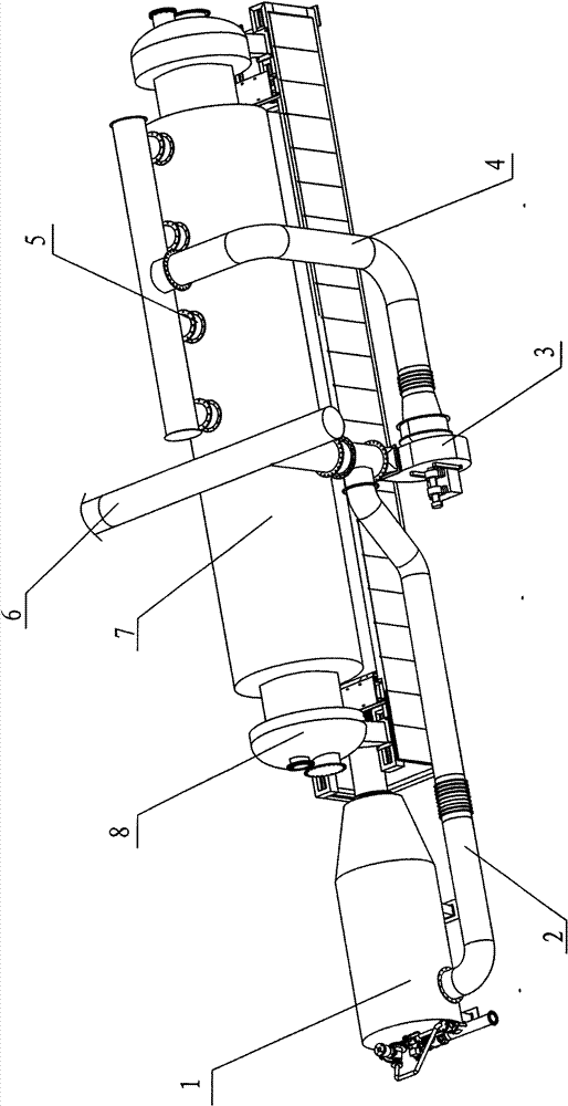
[0003] The existing treatment method generally adopts the heating and cracking method of the cracker to achieve the above-mentioned oily purpose. The cracking temperature is generally around 450°C, but since the heating temperature must be higher than the cracking temperature, under the heating temperature condition, it will be at Coking is formed on the inner wall of the cracker, and the coking phenomenon will become more serious with the increase of heating temperature. The coking on the inner wall of the cracker will bring many harmful effects, such as:
[0004] 1. Coking will prevent the transfer of heat to the material in the cracker and reduce the thermal efficiency;
[0005] 2. Because the heat transfer is hindered, in order to ensure the cracking temperature of the material in the cracker, the temperature of the hot air must be increased to ensure the cracking temperature, which not only increases the fuel consumption, but also greatly reduces the service life of the cracker due to the increase in the heating temperature;
[0006] 3. The coking formed in the cracker will continue to grow on the inner wall, which hinders the flow of materials and increases the pressure difference of the material flow, thereby affecting the movement of materials in the cracker and consuming more energy;
[0007] 4. After coking, it will affect the cracking reaction of the material in the cracker and produce unnecessary side reactions, thus affecting the yield of the final product. In this way, more raw materials and energy must be consumed to obtain the same target product
[0008] Due to the above reasons, the existence of coking will cause the industrial production of pyrolysis to be unable to continue continuously, and cause serious safety hazards in production and equipment

Method used


Image

  • Anti-coking process of oiling device and automatic decoking device
  • Anti-coking process of oiling device and automatic decoking device

Examples


Embodiment 1

[0027] An anti-coking process. The hot air discharged from the cracker is directly delivered to the hot air inlet of the cracker through a pipeline, mixed with the high temperature hot air that will be sent to the cracker before entering the cracker, and then enters the hot air cavity of the cracker. After measurement, the temperature of the hot air discharged from the cracker is 410-420°C, and the temperature at the heater outlet (before mixing) is 1200°C. After mixing, the temperature of the hot air acting on the inner wall of the cracker is 500-550°C. The outlet temperature is 380-400°C. The coking phenomenon on the inner wall of the cracker has been improved.

Embodiment 2

[0029] An anti-coking process. The hot air discharged from the cracker is directly sent to the regenerative fan through the pipeline, and the air volume is increased by the regenerative fan and then sent to the hot air inlet of the cracker. The high-temperature hot air that will be sent to the cracker before entering the cracker After mixing, enter the cracker hot air cavity. After measurement, the temperature of the hot air discharged from the cracker is 415-420°C, and the temperature of the hot air at the heater outlet is 1300°C. After the air volume is increased by the regenerative fan, and after mixing, the temperature of the hot air acting on the inner wall of the cracker is 520- 540℃, the temperature of the oil and gas outlet of the cracker is 380-400℃. The coking phenomenon on the inner wall of the cracker has been improved.

Embodiment 3

[0031] An anti-coking process. The temperature of each hot air outlet of the cracker is measured by a temperature control device, and the air volume of each air outlet is adjusted through a wind control valve. The hot air discharged from each air outlet is mixed through the pipeline and directly sent to the heat recovery fan. The hot air blower increases the air volume and sends it to the hot air inlet of the cracker. It is mixed with the high temperature hot air that will be sent to the cracker before entering the cracker in the mixing chamber, and then enters the cracker hot air chamber. After measurement, the temperature of the hot air discharged from the cracker is 400-410°C, and the temperature of the hot air at the heater outlet is 1270°C. After the air volume is increased by the regenerative fan, the ratio of the hot air discharged from the cracker to the high-temperature hot air that will be sent to the cracker After mixing with a ratio of 2-2.5:1, the temperature of the...


PUM


Abstract

The invention relates to an energy-saving anti-coking process in an oiling device, in particular to a process for reducing temperature difference for reaction by using a heat energy recycling system and setting a special decoking device in a cracker. The process is realized by mixing hot air exhausted in the decoking process with high-temperature hot air to be sent to the cracker before entering the cracker to reduce the temperature difference in the cracker. By adopting the process, the invention fully utilizes waste heat in the cracker, regulates the reaction temperature in the whole decoking process, greatly reduces the temperature difference so as to prevent coking phenomenon caused by great temperature difference in the reaction process; besides, as the special decoking device is assistantly used, the invention completely solves the coking problem in a cracking reactor, improves the reaction efficiency, reduces the load of the device, prolongs the service life of the device, reduces the production cost and decreases the energy consumption.

Description

Technical field [0001] The invention relates to an anti-coking process, in particular to an anti-coking process in oil chemical equipment and an automatic coking cleaning device. Background technique [0002] As we all know, the pyrolysis of waste rubber and plastics can be further processed to produce gasoline, diesel and other products. This not only finds a good solution for the treatment of industrial wastes such as waste tires and other rubber and plastics that are generated in large quantities in modern society, but also has a great impact on resources. Reduction and improvement of energy stress provide new solutions. [0003] Existing treatment methods generally use cracker heating and cracking to achieve the above-mentioned oily purpose. The cracking temperature is generally around 450°C. However, since the heating temperature must be higher than the cracking temperature, it will be Coking is formed on the inner wall of the cracker, and as the heating temperature increases...

Claims


Application Information

Patent Timeline
Patent Type & Authority Patents(China)
IPC IPC(8): C10G1/10C10G1/00
Inventor 牛斌
Owner NIUTECH ENVIRONMENT TECHNOLOGY CORPORATION
Learn More