
Plating limit device, plating equipment using same and plating method using same

A technology of limiting device and electroplating equipment, which is applied in the direction of application, sliding fastener components, fasteners, etc., can solve the problems of no arbitrary bending, limit the coating speed on the zipper strip, and produce spots on the electroplating layer, so as to achieve high electroplating efficiency , Improve the appearance quality, the effect of high appearance quality

Inactive Publication Date: 2009-12-23
FUJIAN SBS ZIPPER SCI & TECH CO LTD
View PDF1 Cites 23 Cited by
  • Summary
  • Abstract
  • Description
  • Claims
  • Application Information

AI Technical Summary

Problems solved by technology

[0003] In the above electroplating process, the zipper strip must be bent to contact the surface of the electroplating guide wheel, and the zipper strip does not have the ability to bend arbitrarily due to the existence of metal elements arranged at intervals
Therefore, during continuous electroplating, it is impossible to ensure that every chain tooth on the zipper is in effective electrical contact with these electroplated guide wheels, thereby affecting the quality of the electroplated zipper
Since these electroplating guide wheels directly contact with the side of the chain teeth of the zipper strip during electroplating, the electroplating reaction interface at this position is destroyed, and problems such as spots are easily generated on the electroplating layer
The side of the chain teeth is directly facing consumers, and the defects on it will seriously affect the overall appearance quality of the zipper.
In addition, since the zipper electroplating equipment uses a conventional electroplating tank for electroplating, the diffusion mass transfer and electromigration mass transfer speed of charged ions in the plating solution are limited, and the reaction particles lost on the electroplating reaction interface cannot be replenished in time, thus limiting the efficiency of the zipper strip. The speed at which the upper layer is formed makes the efficiency of the zipper strip plating not high

Method used


Image

  • Plating limit device, plating equipment using same and plating method using same
  • Plating limit device, plating equipment using same and plating method using same
  • Plating limit device, plating equipment using same and plating method using same

Examples


Embodiment 1

[0035] The chain teeth 64 of the single chain 60 are made of brass. The electroplating equipment 100 is used to electroplate the chain teeth 64 of the single chain 60. The electroplating steps are as follows:

[0036] Preparation before plating includes carrying out surface mechanical treatment to the chain teeth 64 of the single chain 60, such as polishing the chain teeth 64, deburring edges, etc.; degreasing, cleaning, and removing stains on the surface of the chain teeth 64; electroplating, using the The electroplating equipment 100 electroplates the single chain 60 to form an electroplating layer on the surface of the chain elements 64 of the single chain 60 ; after plating, the electroplated single chain 60 is cleaned, dried, and coated with brightener.

[0037] In the above electroplating step, the composition of the electroplating solution is: nickel sulfate 120 g / L, nickel chloride 30 g / L, boric acid 40 g / L, temperature 45°C-55°C, pH value 3.8-4.5. The electroplating c...


PUM


Abstract

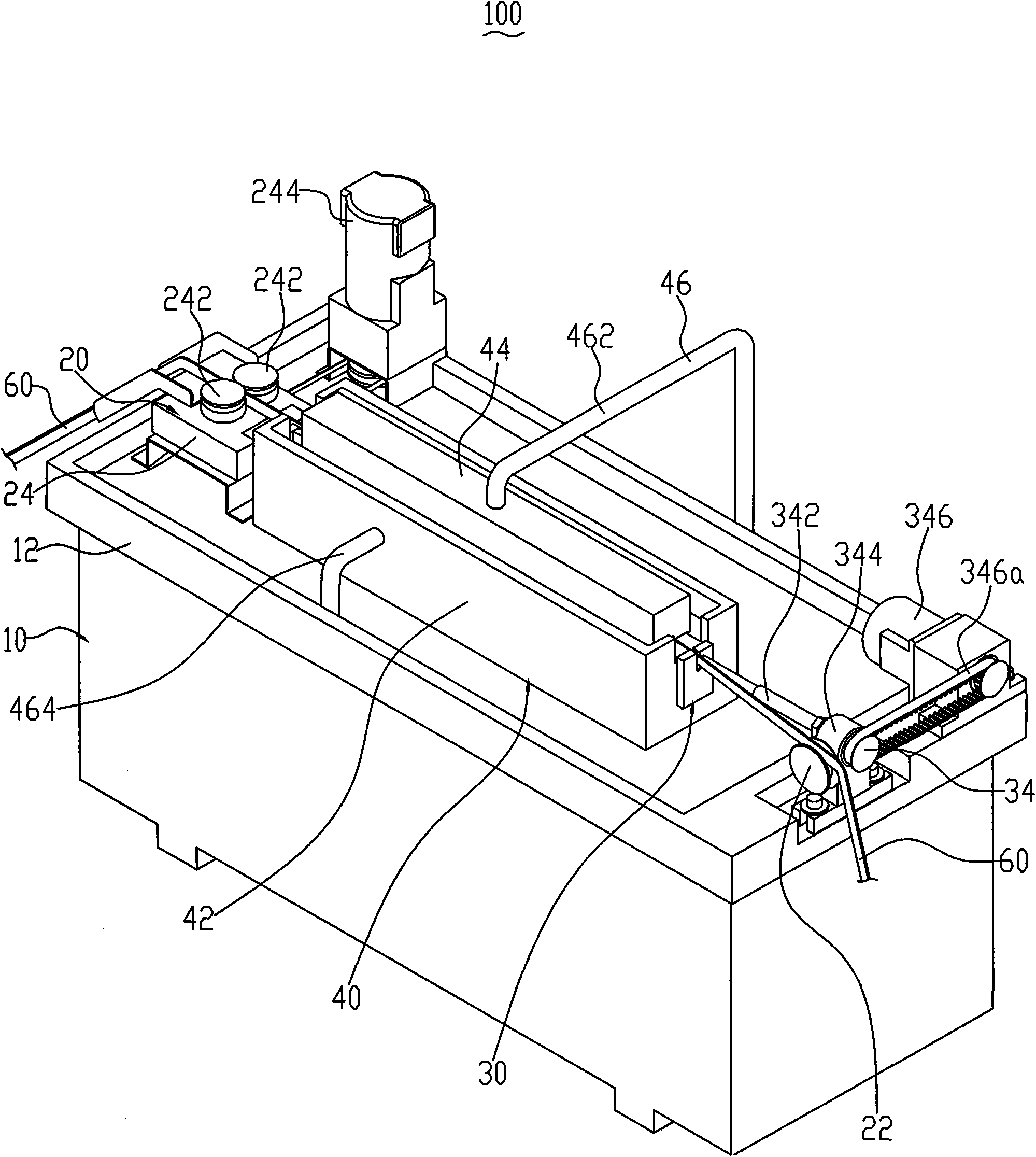
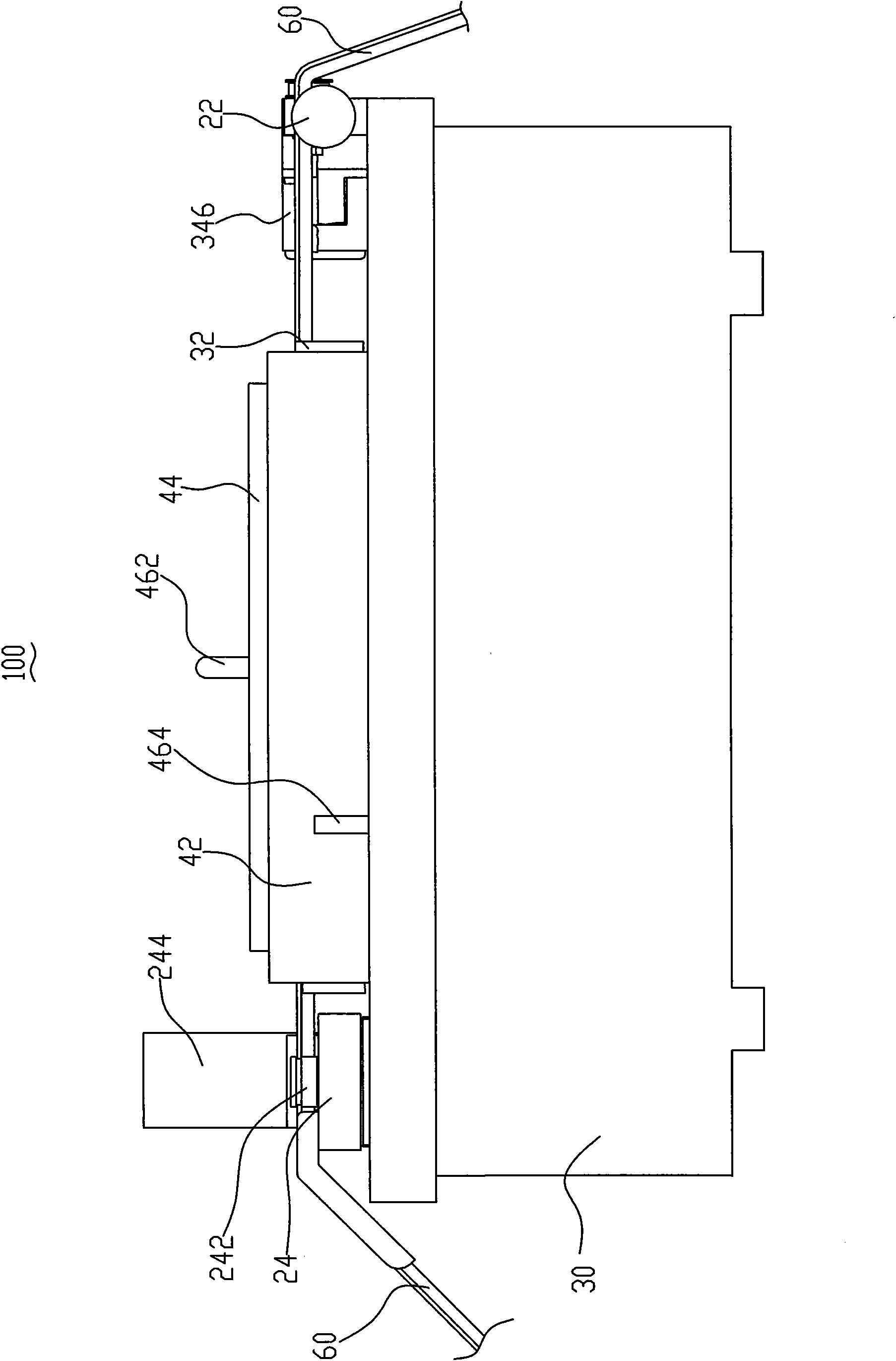
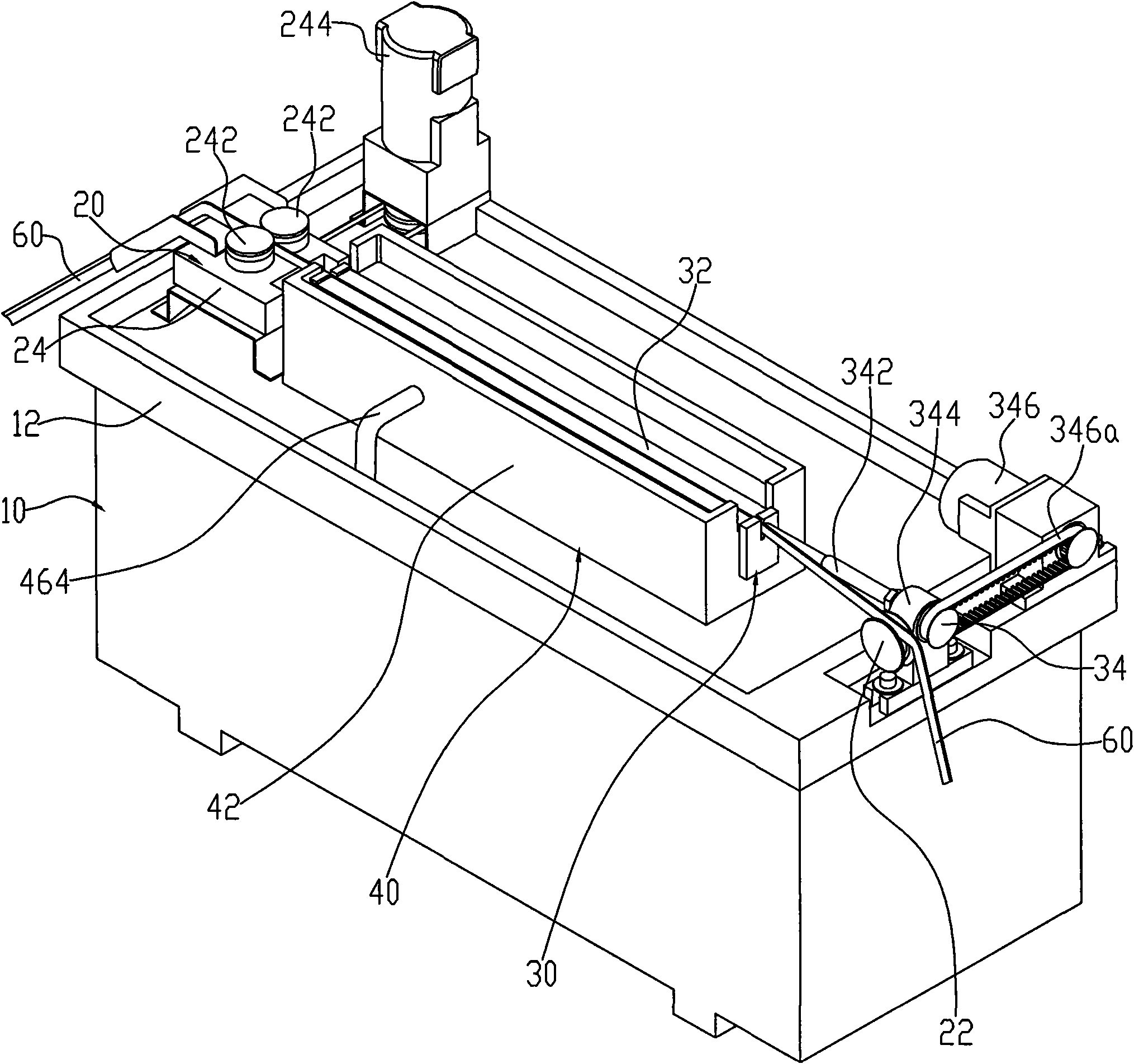
The invention discloses a plating limit device, plating equipment using the same and a plating method using the same. The plating limit device is used for limiting a moving zipper in a plating process and comprises a plating cathode and a tensioning mechanism, wherein the top face of the plating cathode is provided with an opening, cloth belts of the zipper runs through the opening of the plating cathode; and the tensioning mechanism is used for applying a tensile force toward the plating cathode onto the zipper to allow the bottom of zipper teeth on the cloth belts of the zipper to be pressed against and connected with two sides of the opening of the plating cathode and to be electrically connected with the plating cathode. The plating equipment using the plating limit device and the plating method using the plating limit device have the advantages of high plating quality and high plating efficiency.

Description

technical field [0001] The invention relates to an electroplating limiting device, electroplating equipment and an electroplating method using the device, in particular to an electroplating limiting device for electroplating zippers, an electroplating equipment and an electroplating method using the limiting device. Background technique [0002] At present, in order to enhance the aesthetics and improve the wear resistance and corrosion resistance, the industry usually uses metal deposition to plate the surface of the upper chain teeth of the zipper chain belt. Commonly used metal deposition methods are electroless plating and electroplating. When electroless plating is used for plating, a zipper with good wear resistance cannot be obtained because the plating layer is not dense. When electroplating is used for plating, although the obtained plating layer is dense enough, how to energize the chain elements arranged at intervals on the non-conductive zipper chain tape has be...

Claims


Application Information

Patent Timeline
IPC IPC(8): C25D7/02
Inventor 陈瑞森
Owner FUJIAN SBS ZIPPER SCI & TECH CO LTD
Learn More