Swing mirror angle scanning characteristic test device for camera

A test device and angle scanning technology, which is applied in the field of camera swing mirror swing angle scan characteristic test device, can solve the problems that non-contact measurement cannot be realized, non-contact measurement is not solved, and the use range is limited, so as to simplify the measurement steps, The effect of eliminating angle drift and improving the efficiency of measurement

Inactive Publication Date: 2009-12-23
BEIJING INSTITUTE OF TECHNOLOGYGY
View PDF0 Cites 17 Cited by
  • Summary
  • Abstract
  • Description
  • Claims
  • Application Information

AI Technical Summary

Problems solved by technology

[0006] The circular grating angle measurement system has the advantages of good repeatability, large measurement angle, and small nonlinear error, so it is widely used in the field of angle measurement. With the development of optoelectronic technology in recent years, it can be combined with photoelectric detection technology to realize digital measurement. Its measurement accuracy and efficiency show great development potential, but because it needs to be driven by the measured object during the measurement process, it cannot realize non-contact measurement, so its application range is greatly limited
In recent years, the combination of circular grating and photoelectric detection technology has enabled the rapid development of angle automatic measurement technology. The British RENISHAW company has developed a high-precision dual-reading head circular grating angle measurement system, which has achieved high accuracy. However, it has not solved the problem of Problems with contact measurement
However, the use of circular grating angle measurement system combined with high-precision small swing angle angle measurement technology to expand the angle measurement range and realize non-contact dynamic measurement has not been reported so far.

Method used


Image

  • Swing mirror angle scanning characteristic test device for camera
  • Swing mirror angle scanning characteristic test device for camera
  • Swing mirror angle scanning characteristic test device for camera

Examples


Embodiment Construction

[0026] The present invention will be further described below in conjunction with drawings and embodiments.

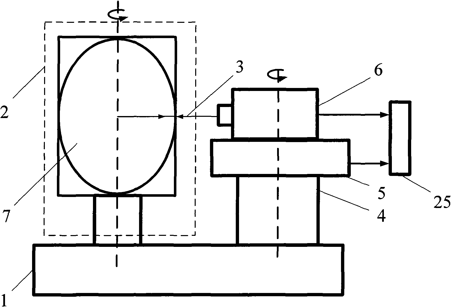
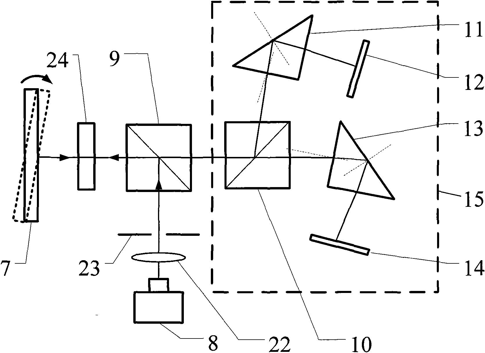
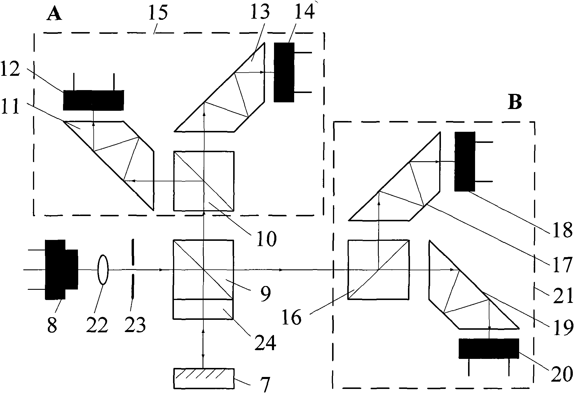
[0027] The technical principle of the present invention is: using differential internal reflection goniometric technology to place the reflectors of the small-angle non-contact tracking dynamic goniometric optical path in the reflection and transmission directions of the beam splitter respectively to form a differential critical reflection structure. The light intensity signals from different angles detected by the detector can realize high-precision tracking measurement of the measured angle through calculation; in addition, the introduction of a high-precision circular grating angle measurement system, combined with the data fusion processing system, expands the system range and realizes dynamic Measurement.

[0028] The structure of the test device for the scanning characteristics of the swing mirror swing angle of the camera of the present invention is as follows: ...


PUM


Abstract

The invention belongs to the technical field of optical precision measurement, and relates to a swing mirror angle scanning characteristic test device for a camera. The device mainly comprises a high-stability workbench, a swing mirror angle scanning system fixed at one end of the high-stability workbench, a high-precision rotation system fixed at the other end of the high-stability workbench, a high-precision circular grating angle measuring system fixed on the high-precision rotation system, and a small-angle high-precision angle measuring system fixed on the circular grating angle measuring system. The combination of the small-angle high-precision angle measuring system and the high-precision circular grating angle measuring system in the device can carry out large-angle high-precision accurate measurement for a sample, realize non contact of a measurement process and dynamic tracking for the sample at the same time, and provide powerful detection and correction means for swing mirror scanning characteristics of the cameras used in satellites and aerial photography, and the like.

Description

technical field [0001] The invention belongs to the technical field of optical precision measurement, and relates to a camera swing mirror swing angle scanning characteristic test device, which can be used for the scan angle resolution, scan angular velocity, scan uniformity, scan angle repeatability, scan linear segment time, effective Large-angle high-precision dynamic non-contact measurement of parameters such as scanning field of view and scanning frequency. technical background [0002] The scanning pendulum mirror is a key component of the camera in high-altitude reconnaissance equipment such as satellites and early warning aircraft. Its performance directly affects the satellite's earth observation resolution and field of view. Angular velocity, scanning uniformity (linearity), scanning angle repeatability, scanning linear segment time, effective scanning field of view, scanning frequency, etc. are calibrated with high precision to facilitate the stitching, calculatio...

Claims


Application Information

Patent Timeline
IPC IPC(8): G03B43/00G01M11/00G02B27/28
Inventor 赵维谦邱丽荣王允田丽
Owner BEIJING INSTITUTE OF TECHNOLOGYGY
Why Eureka
Try Eureka