Calibration method of ultrasonic flaw detection and quality control method and production method of tubular body

A calibration method and quality management technology, which is applied to the analysis of solids using sound waves/ultrasonic waves/infrasonic waves, material analysis using sound waves/ultrasonic waves/infrasonic waves, and processing detection response signals. Insufficient detection performance, etc.

Active Publication Date: 2009-12-30
JFE STEEL CORP
View PDF5 Cites 13 Cited by
  • Summary
  • Abstract
  • Description
  • Claims
  • Application Information

AI Technical Summary

Problems solved by technology

First of all, in the method of Patent Document 1, the problem is that since the focused ultrasonic beam has a narrow width, it is necessary to perform flaw detection in the entire area in the depth direction of the welded part (the direction of the steel pipe wall thickness), requiring a plurality of channels. Not only does the equipment cost increase, but also it is very troublesome to adjust the position when the size of the tube is changed.
Also, when the shape of the defect is not a pore but is located inside the wall thickness in a planar shape like a penetrating defect or a cold joint, the reflected wave travels in a direction different from the incident direction, making detection difficult
[0008] In addition, in the method of Patent Document 2, since one array probe is sufficient, and the setting at the time of size conversion can also be performed electronically, the former problem shown in Patent Document 1 does not exist, but the latter problem still not resolved
[0009] In addition, when the shape of the defect is p

Method used


Image

  • Calibration method of ultrasonic flaw detection and quality control method and production method of tubular body
  • Calibration method of ultrasonic flaw detection and quality control method and production method of tubular body
  • Calibration method of ultrasonic flaw detection and quality control method and production method of tubular body

Examples


Embodiment 1

[0172] Embodiments of the present invention will be described below with reference to the drawings.

[0173] Figure 28 It is a diagram showing an example of the functional configuration of an ultrasonic flaw detection device related to tandem flaw detection. In the object size input unit 30 , an operator or a processing computer inputs the outer diameter and wall thickness of the steel pipe used for flaw detection. In the array probe storage unit 31 , the number of frequencies, the pitch of transducers, and the number of transducers of the array probe 5 are stored.

[0174] The aperture width control unit 32 controls the aperture width corresponding to the beam width (beam size) during transmission and reception, and calculates the position of the array probe, the number of scanning lines for transmission, and the number of scanning lines for each scan according to the size of the steel pipe and the specification of the array probe. The path of the beam used for the launch ...

Embodiment 2

[0204] Next, use Figure 29 A structural example in which the ultrasonic flaw detection method described in Example 1 is applied to the manufacturing process of an electric seam steel pipe will be described. Figure 29 The devices in include an unwinding machine 151 for providing a strip, a straightening machine 152 for correcting a shape, a calender forming machine 154, a fin forming machine 155, an induction heating device 156, a squeeze roll 157, and a sorting machine 158, such as A strip plate with a plate width of 1920 mm×a plate thickness of 19.1 mm was electric seam welded, and a steel pipe of φ600 was manufactured by a classifier 158 . 159 is a pipe cutting machine among the figure.

[0205] Here, the array probe 5 for tandem flaw detection is disposed, for example, on the inlet side or the outlet side of the sorter 158 after welding, or on the outlet side of the pipe cutter 159, and the mechanical characteristics are evaluated based on the results, thereby enabling q...

Embodiment 3

[0209] Embodiment 1 and Embodiment 2 described examples in which sensitivity correction was performed on a steel pipe, but the same correction method can also be applied to the case of using a C-scan other than a steel pipe, which will be described below.

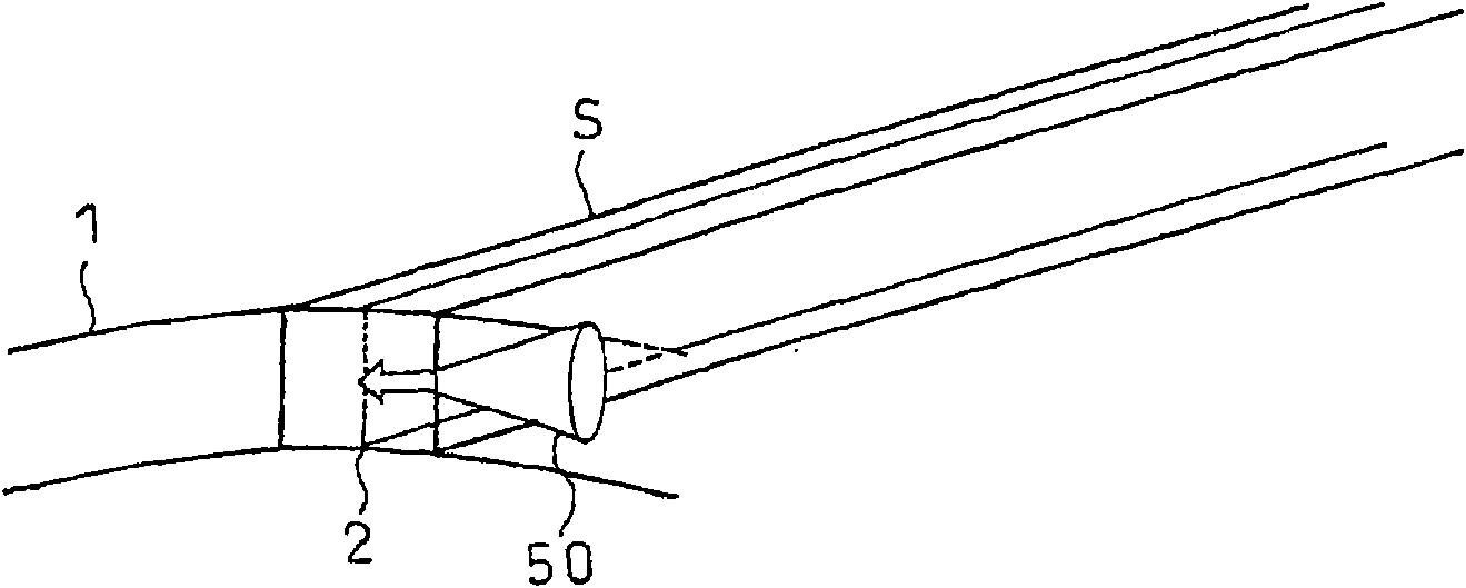
[0210] An example of a structure for implementation using the C-scan method is shown in Figure 30 superior. It is composed of the following: a probe 50, which transmits and receives ultrasonic waves to the cut-out welding surface for ultrasonic flaw detection; an ultrasonic transmitting and receiving unit 52, which controls the sending and receiving of ultrasonic waves in the probe 50; Carry out C-scanning on the welding surface, so that the probe scans sequentially along the direction of the tube axis and the direction of the tube thickness; the received signal storage unit 56 stores the C-scan data; the signal processing unit 58 performs calculation processing on the C-scan data; the parameter input unit 60 uses Paramet...


PUM

PropertyMeasurementUnit
Beam widthaaaaaaaaaa

Abstract

Ultrasonic flaw detection at the welded portion (2) of a tubular body (1) is performed at least in the axial direction of the tubular body, a defect judgment threshold is determined based on the difference of signal strength between the total area of defects existing in the region of an ultrasonic beam on the welded surface and an artificial defect, and then quality control of the tubular body isperformed by the defect judgment threshold. From the defect density on the welded surface at the welded portion in the axial direction of tubular body determined from a desired quality level and the area of the ultrasonic beam on the welded surface, an equivalent defect diameter is determined based on the total area of defects existing in the region of the ultrasonic beam and then the defect judgment threshold is determined based on the difference of signal strength between the equivalent defect diameter and the artificial defect.

Description

[0001] technology area [0002] The present invention relates to an ultrasonic flaw detection correction method for detecting microscopic defects occurring in welded portions of welded steel pipes with high precision, a pipe body quality control method, and a manufacturing method. Background technique [0003] The quality of welded parts is very important in welded steel pipes, and in-line flaw detection of welded parts is generally performed by ultrasonic oblique flaw detection in the manufacturing process. This method is as follows: Ultrasonic waves are incident obliquely on the testing surface of the testing material, and the inner and outer surface defects and internal defects of the testing material are detected from the reflected waves reflected by the defects. Usually, for example, in electric resistance welded steel pipes, the reflection method is applied to an ultrasonic beam with a 5 MHz and a refraction angle of 45° to detect mm-sized defects, such as defects such a...

Claims


Application Information

Patent Timeline
IPC IPC(8): G01N29/30G01N29/44G01N29/04
CPCG01N2291/0289G01N29/11G01N2291/2675G01N2291/044G01N29/30G01N2291/02854
Inventor 饭塚幸理剑持一仁横山泰康井上智弘坂下重人
Owner JFE STEEL CORP
Why Eureka
Try Eureka