
Method and system for wide-spectrum and high-resolution detection based on space-time light splitting in OCT

A detection method and spectral resolution technology, which is applied in the field of optical coherence tomography, can solve the problems of reduced imaging quality, spectral resolution, spectral domain OCT imaging depth, and different focusing positions of different colors of light, so as to improve the signal-to-noise ratio, Eliminate spectral crosstalk and reduce field of view

Inactive Publication Date: 2011-05-04
ZHEJIANG UNIV
View PDF0 Cites 0 Cited by
  • Summary
  • Abstract
  • Description
  • Claims
  • Application Information

AI Technical Summary

Problems solved by technology

Since the increase in the number of linear CCD pixels means an increase in the field of view, unless a more complex optical imaging system is designed, serious field curvature will inevitably appear on the image surface (CCD photosensitive surface), and due to the spectral range If it is too wide, the dispersion phenomenon is serious, resulting in different focusing positions of different colors of light, which makes the spectrometer unable to completely separate the various colors of light and introduces cross-talk (cross-talk), the detection signal-to-noise ratio decreases and the axial resolution of the system decreases, ultimately reducing the imaging quality
Reducing the spectral resolution of the spectrometer means reducing the imaging depth of spectral domain OCT

Method used


Image

  • Method and system for wide-spectrum and high-resolution detection based on space-time light splitting in OCT
  • Method and system for wide-spectrum and high-resolution detection based on space-time light splitting in OCT
  • Method and system for wide-spectrum and high-resolution detection based on space-time light splitting in OCT

Examples


Embodiment Construction

[0024] Below in conjunction with accompanying drawing and embodiment example, the present invention will be further described:

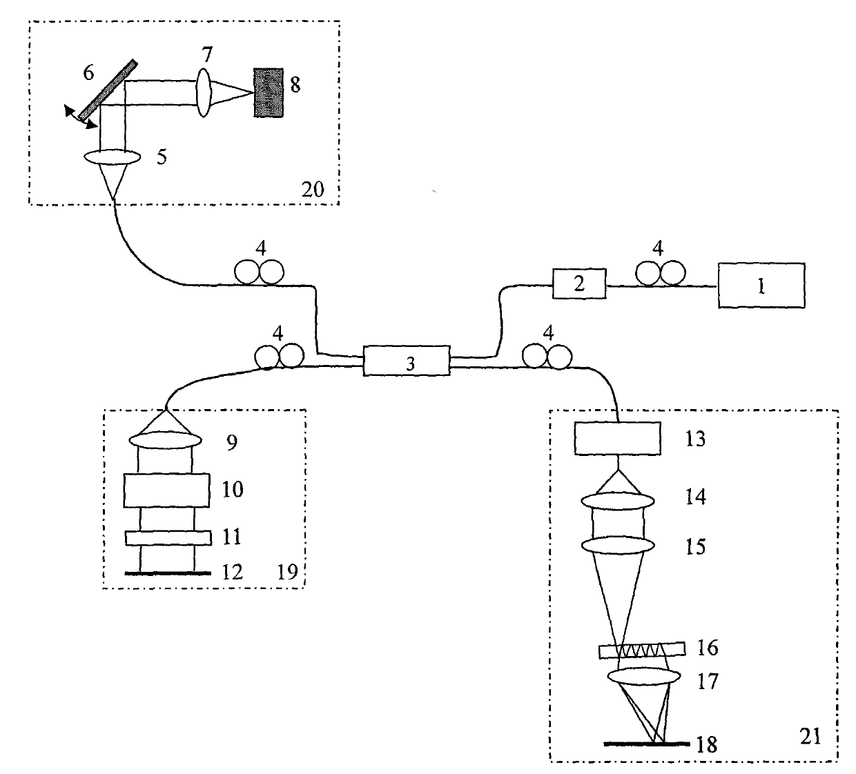
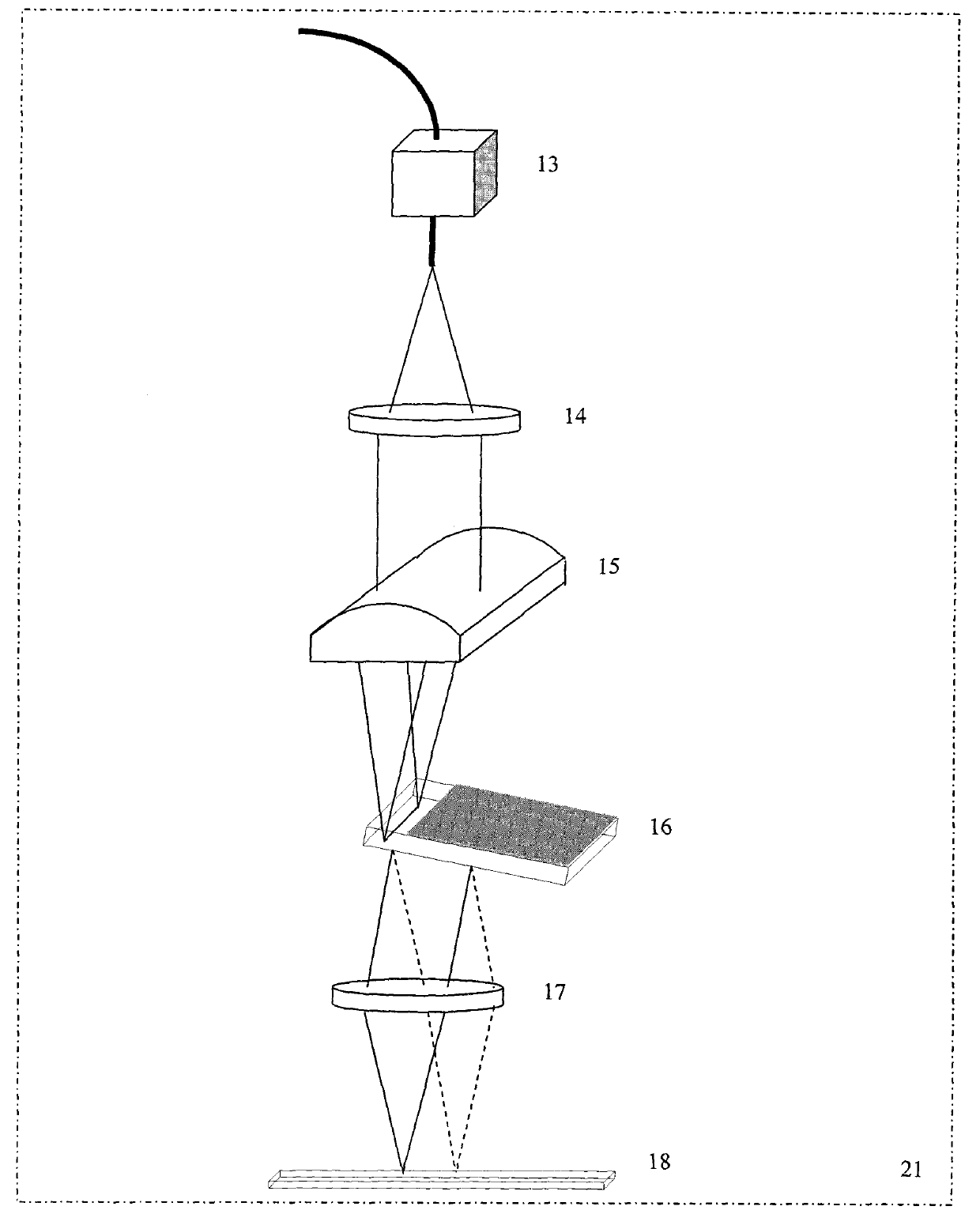
[0025] Such as figure 1 , figure 2 As shown, the present invention includes a broadband light source 1 , an optical isolator 2 , a broadband fiber coupler 3 , four polarization controllers 4 , a reference arm 19 , a scanning probe 20 and a detection arm 21 . The low-coherent light from the broadband light source 1 enters the broadband fiber coupler 3 through the first polarization controller 4 and the optical isolator 2. After splitting, it enters the scanning probe 20 through the second polarization controller 4 and is collimated. After the lens 5, the scanning galvanometer 6 and the focusing lens 7 irradiate the sample 8, the original path returns to the broadband fiber coupler 3 through the second polarization controller 4; the other path enters the reference arm 19 through the third polarization controller 4, and passes through the The collima...


PUM


Abstract

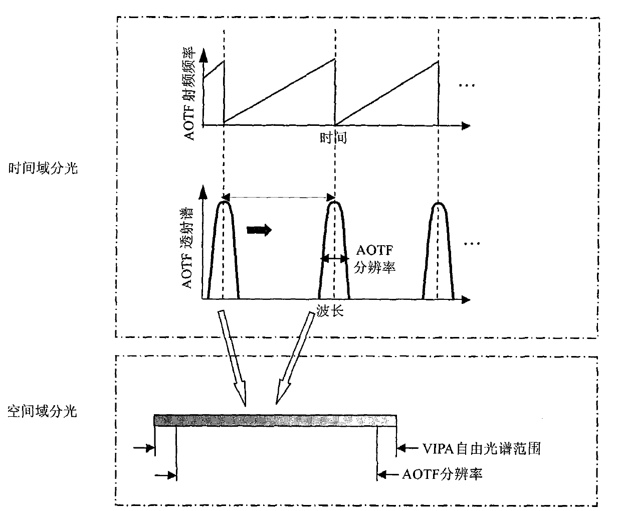
The invention discloses a method and a system for wide-spectrum and high-resolution detection based on space-time light splitting in OCT. Low-coherence lights emitted from a broadband light source enter a broadband optical fiber coupler through an optical isolator, and respectively enter a scanning probe and a reference arm after light splitting by the coupler. The returned lights generate interference in the broadband optical fiber coupler, a detection arm detects interference signals after the interference signals are decomposed into different spectral components, and then the interference signals are sent to a computer so as to reconstruct a sample image. In the detection arm, interference spectral signals firstly pass through a time domain light splitting device with low resolution and wide free spectrum range, then pass through a space domain light splitting device with high resolution and narrow free spectrum range, and then are detected by a spectrum imaging system. On the premise of satisfying the requirement of high spectrum resolution, the invention can reduce a visual field of the spectrum imaging system, and solves the problems of field curvature, spectrum interferenceand the like existing during large visual field spectrum imaging, thereby spectral domain OCT imaging with high signal-to-noise ratio and high resolution is realized.

Description

technical field [0001] The invention relates to optical coherence tomography (OCT) technology, in particular to a system of a wide-spectrum high-resolution detection method based on time-space spectroscopy in OCT. Background technique [0002] Optical coherence tomography (OCT for short) can perform non-contact, non-invasive, high-resolution in vivo imaging of internal tissue structure and physiological functions in vivo, and has a wide range of applications in the field of biomedical imaging. [0003] The current spectral domain OCT system uses a high-speed linear array CCD to collect the spectral components of the interference signal in parallel, and can obtain the depth information of the sample without axial scanning. It has the characteristics of fast and high sensitivity. The core of the system is the fast spectrometer in the detection arm. . In the OCT system, the axial resolution of the system is inversely proportional to the bandwidth of the light source. The wider...

Claims


Application Information

Patent Timeline
Patent Type & Authority Patents(China)
IPC IPC(8): A61B5/00A61B3/00G01N21/45
Inventor 丁志华王川王凯孟婕陈明惠吴彤
Owner ZHEJIANG UNIV
Learn More