
Collimating solar energy collector

A solar energy collection and collimation technology, which is applied in the direction of solar thermal devices, solar collectors, solar collector controllers, etc., can solve the problem of reducing the net output power and efficiency of the system, the complexity of the dish group system, and the complexity of the tracking system and other problems, to achieve the effect of novel and reasonable design, easy operation and good collection effect

Inactive Publication Date: 2011-07-27
赵明生 +1
View PDF0 Cites 0 Cited by
  • Summary
  • Abstract
  • Description
  • Claims
  • Application Information

AI Technical Summary

Problems solved by technology

But its disadvantages are: the investment of the heliostat field is too large, due to the complexity of its tracking system, it accounts for more than half of the entire investment; and the boiler should be installed at a high altitude, the larger the collection area, the higher the height of the tower The higher the tower, the greater the investment in the tower; the higher the tower, the farther the energy transmission distance will be, but at the same time the loss will be greater
But its disadvantages are: the energy depends on pipelines and pumps in the process of concentration, the pipeline system is much more complicated than the tower power station, and the loss of heat and resistance is large, which reduces the net output power and efficiency of the system
[0006] 3) The disc-type trough collection device is divided into two types: disc group type and independent disc type. Among them, the disc group type system is complicated, and the cost of pipelines and heat insulation materials is very high. Because of its limitations, it has not been developed; for the independent disc type Since power generation cannot be used for large-scale power generation, no industry analysis will be conducted on it

Method used


Image

  • Collimating solar energy collector
  • Collimating solar energy collector
  • Collimating solar energy collector

Examples


Embodiment Construction

[0044] Such as Figure 4 , Figure 5 and Figure 6 As shown, the present invention includes a heat-collecting boiler 5 installed horizontally on the ground and capable of light-to-heat conversion and thermal energy storage, and a plurality of light-collecting units 6 arranged around the heat-collecting boiler 5. The light-collecting units 6 The number is n. The lower part of the heat collecting boiler 5 has a row of multiple light inlets 5-1 along the circumferential direction, the plurality of light inlets 5-1 are evenly arranged and the number of light inlets 5-1 is m, n=i×m , where i is a positive integer and i=1~400, The light output port of each light collecting unit 6 corresponds to one light entrance hole 5-1. In actual arrangement, for the convenience of operation, a plurality of light-collecting units 6 can be arranged on the peripheral side of the heat-collecting boiler 5 along the circumferential direction, and the plurality of light-collecting units 6 are even...


PUM


Abstract

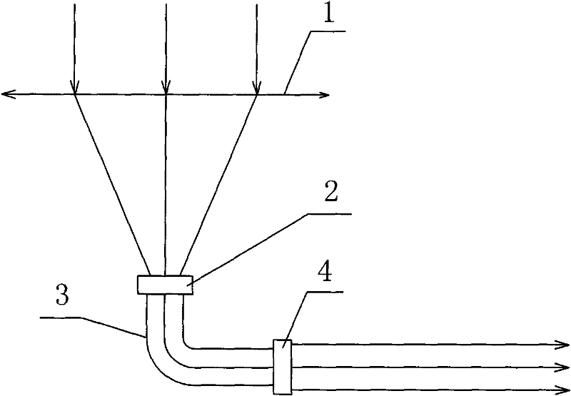
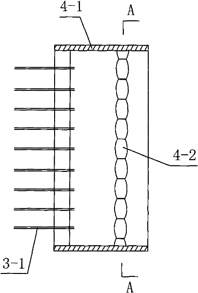
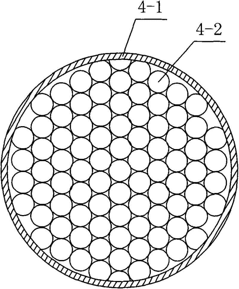
The invention discloses a collimating solar energy collector comprising a heat-collecting boiler and a plurality of light-collecting units arranged on the peripheral side of the heat-collecting boiler, wherein, a row of multiple light-ingoing holes in uniform distribution are arranged at the lower part of the heat-collecting boiler along the circumferential direction; the light-collecting units and the light-ingoing holes are identical in quantity, and the light-output holes of the light-collecting units are just opposite to the corresponding light-ingoing holes respectively; each light-collecting unit consists of a Fresnel lens which always carries out condensation by facing the sun directly, a fiber coupling element located at the lower focal point of the Fresnel lens, a fiber bundle connected with the fiber coupling element, and a fiber bundle collimator mounted at the light-output terminal of the fiber bundle and used for collimating the scattered light transmitted from the fiber bundle into a horizontal light bundle and outputting the horizontal light bundle. The invention has the advantages of novel and reasonable design, convenient manufacture and installation, low cost, good using effect, high light-heat conversion efficiency and wide application range; and the invention can effectively overcome various shortcomings in the existing solar energy collectors.

Description

technical field [0001] The invention relates to a solar heat collection device, in particular to a collimated solar energy collection device. Background technique [0002] Existing solar heat collection devices mainly include the following three types: 1) tower type collection device; 2) trough type collection device; 3) dish type collection device. The solar heat collection device is mainly used for solar power generation in industrial applications, so the corresponding power generation methods are also called tower power generation, trough power generation and butterfly power generation. [0003] In actual use, the respective characteristics and deficiencies of the above three solar heat collection devices are as follows: [0004] 1) Tower collection device: Arrange a large number of heliostats (a spherical mirror group that automatically tracks the sun) on the ground, and build a high tower at a suitable position among the above-mentioned group of heliostats, and place a...

Claims


Application Information

Patent Timeline
Patent Type & Authority Patents(China)
IPC IPC(8): F24J2/38F24J2/46G02B6/26G02B1/00G02B1/02F24S50/20
CPCY02E10/47
Inventor 赵明生田应芹赵辉
Owner 赵明生
Learn More