
Automatic detection method of particle size distribution

A particle size and automatic detection technology, applied in the detection field, can solve the problems of long analysis time, unrealized full automation, and consuming processor operation time, etc., and achieve the effect of shortening the calculation time

Inactive Publication Date: 2010-01-06
SHANGHAI JIAO TONG UNIV
View PDF0 Cites 47 Cited by
  • Summary
  • Abstract
  • Description
  • Claims
  • Application Information

AI Technical Summary

Problems solved by technology

[0004] However, there are deficiencies in the technical method described in this article: (1) "Adopting adaptive threshold value segmentation and boundary chain code image processing technology", it will inevitably cause a large amount of processor calculation and too long analysis time; (2) ) system device is more complex
[0006] However, the technical method described in this article also has shortcomings: (1) "set the gray value threshold, binarize, separate the images of the particles that are in contact with each other, set the measurement content, detection range, detection, etc., and then The measurement data of multiple images is transferred to Excel 5.0 for cumulative calculation, and the average particle size and particle size distribution width are obtained, and the particle size distribution diagram is drawn." It shows that the entire calculation process has not yet been fully automated; (2) "Measurement of all particles area, and convert it to the diameter of an equivalent circle (because the particle size of the contact boundary is uncertain, so it is not considered)" will consume a lot of processor computing time

Method used


Image

  • Automatic detection method of particle size distribution
  • Automatic detection method of particle size distribution
  • Automatic detection method of particle size distribution

Examples


Embodiment Construction

[0050] The embodiments of the present invention are described in detail below in conjunction with the accompanying drawings: this embodiment is implemented on the premise of the technical solution of the present invention, and detailed implementation methods and specific operating procedures are provided, but the protection scope of the present invention is not limited to the following the described embodiment.

[0051] In an embodiment, the automatic detection method of particle size distribution comprises the following steps:

[0052] The first step, image preprocessing

[0053] The measured image is converted from RGB space to HSV space, thereby obtaining the chroma, brightness and saturation components of the original image, and then performing Gaussian smoothing filtering and histogram equalization on each component.

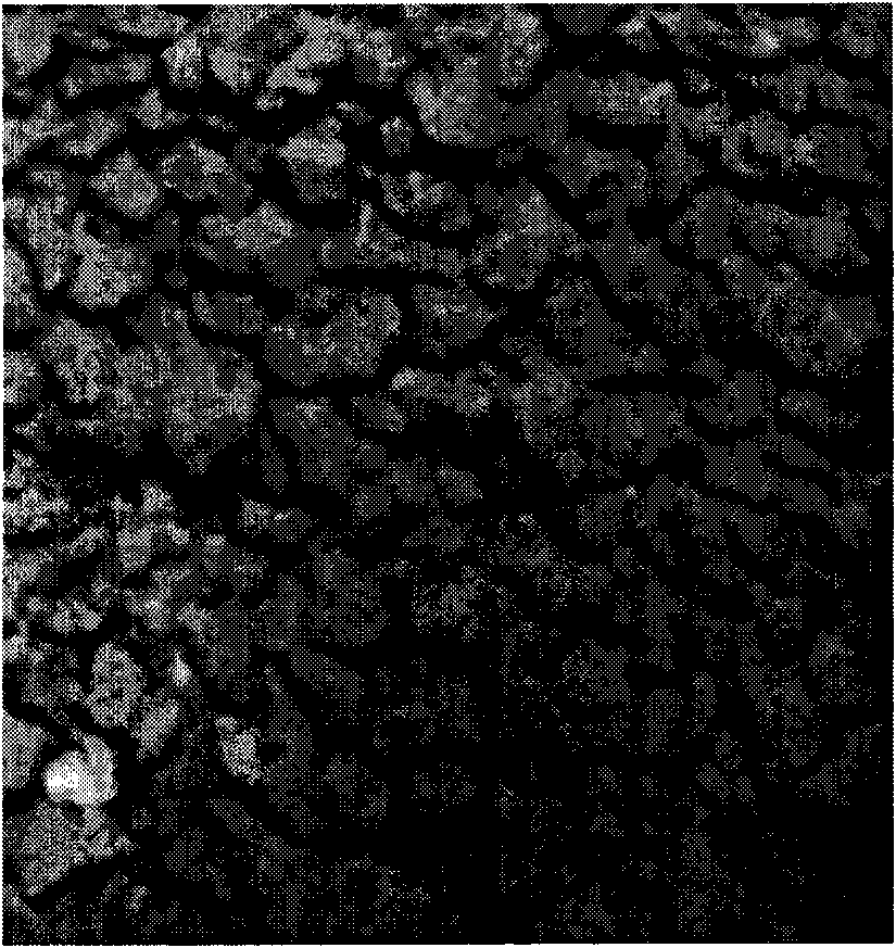
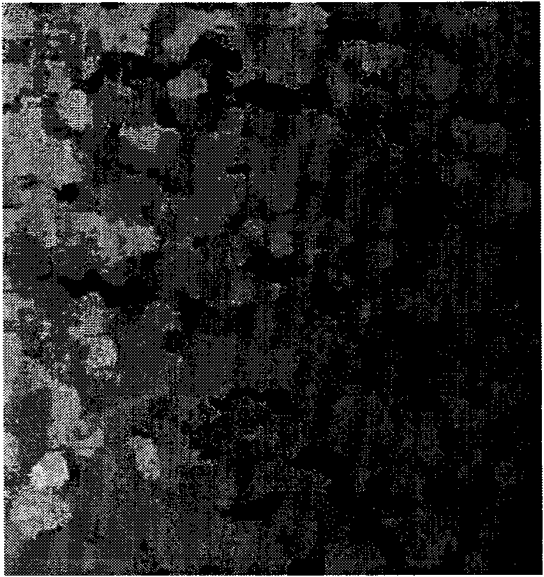
[0054] For example figure 1 The collected original image is converted into HSV space expression from the RGB space expression of image color by using (Fo...


PUM


Abstract

The invention relates to an automatic detection method of particle size distribution, which is characterized by comprising the following steps: step one, preprocessing images, converting images to be detected into HSV space from RGB space, acquiring chroma, brightness and saturation components of the images to be detected, carrying out Gaussian smoothing filter and histogram equalization to all components and automatically enhancing the brightness, the color and the contrast of the images; step two, carrying out morphological smoothing of color images so as to avoid images caused by the effect of shadow and reflected light; step three, judging a particle area and a centroid thereof and eliminating pseudo-boundary points positioned on the surfaces of particles after completing the process of boundary extraction operation, wherein the pseudo-boundary points have the characteristics of boundary points but are not boundary points ; step four, expanding particles maximumly and carrying out maximum expansion operation of the particle area, i.e. dividing the whole material surface into a plurality of parts according to the principle of proximity to one of the particles; step five, calculating particle size by a double-circle method; and step six, calculating particle size distribution. Accordingly, the invention provides direct information reference of particle size distribution for follow-up decision operation of industrial process control.

Description

technical field [0001] The invention relates to a method in the technical field of detection, in particular to an automatic detection method for particle size distribution. Background technique [0002] Most of the raw materials in the industrial production process are irregular shapes, such as ore in the ironmaking process, and their volume, scale and shape are varied. These raw materials participate in the chemical reaction process. How to make the particles of different sizes evenly distributed will be one of the quality assurance conditions for chemical reactions. The commonly used methods for automatic detection of particle size distribution are: 1. With the help of particle centrifugal force field, measure the particle size distribution through an optical unit to measure the relevant change parameters; 2. Use laser and its polarization device to realize particle size distribution by observing the change of beam Measurement of size distribution; 3. Method based on imag...

Claims


Application Information

Patent Timeline
IPC IPC(8): G01N15/02G06T7/00
Inventor 张秀彬应俊豪焦东升钱斐斐
Owner SHANGHAI JIAO TONG UNIV
Learn More