Switching method of built-in antenna and exposed antenna of FM receiver as well as terminal thereof

A technology of external antenna and built-in antenna, applied in the direction of antenna support/mounting device, independent non-interactive antenna combination, electrical components, etc., can solve the impact of FM broadcast reception performance, poor performance antenna reception performance, and inconvenient user operation Convenience and other issues, achieve good promotion significance, realize seamless switching, improve quality and effect

Active Publication Date: 2010-01-13
罗源县产品质量检验所
View PDF0 Cites 29 Cited by
  • Summary
  • Abstract
  • Description
  • Claims
  • Application Information

AI Technical Summary

Problems solved by technology

Most of the FM chips used in current terminals use earphones as FM receiving antennas, so users must plug in earphones if they want to listen to FM.
If you want to switch to the speaker to listen to FM, you must also plug in the earphone, which makes the operation very inconvenient for the user
In order to meet the needs of users, there are a few manufacturers of FM chips that support the connection of built-in antennas, but experiments have shown that because the built-in antenna is on the motherboard, it will be shielded by the shell and related GSM (Global System for Mobile Communications, Global System for Mobile Communications) , WCDMA (Wideband Code Division Multiple Access, wideband code division multiple access) antenna signal interference and other

Method used


Image

  • Switching method of built-in antenna and exposed antenna of FM receiver as well as terminal thereof
  • Switching method of built-in antenna and exposed antenna of FM receiver as well as terminal thereof

Examples


Embodiment Construction

[0027] The preferred embodiments of the technical solutions of the present invention will be further described in detail below in conjunction with the accompanying drawings.

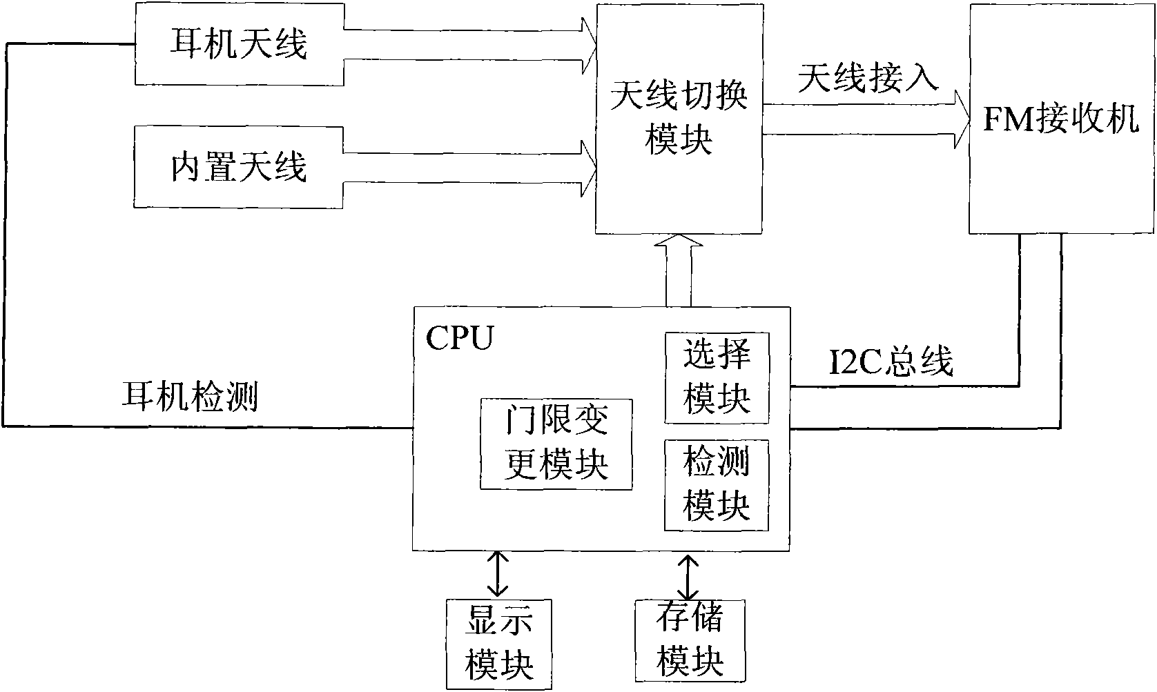
[0028] figure 1 is a schematic diagram of a terminal according to an embodiment of the present invention, and the terminal according to this embodiment of the present invention will be described in detail below.

[0029] The terminal in the embodiment of the present invention includes an FM receiver, a built-in antenna, an external antenna, a CPU, and an antenna switching module.

[0030] The CPU is connected to the FM receiver through the I2C bus. The CPU detects whether an external antenna is connected through the GPIO (General Purpose Input Output) port. The CPU controls the antenna switching module through the GPIO to select the built-in antenna or the external antenna. The antenna The switching module is connected with the FM receiver through the antenna inlet.

[0031] When the terminal is connec...


PUM


Abstract

The invention provides a switching method of a built-in antenna and an exposed antenna of an FM receiver as well as a corresponding terminal thereof. The terminal comprises an FM receiver, the built-in antenna, the exposed antenna, a CPU, a detection module and an antenna switching module. The CPU detects that the exposed antenna is switched in when the terminal switches in the exposed antenna inthe on-state of the FM receiver; the detection module is used for detecting the RSSI of signals received by the built-in antenna and the exposed antenna; the selection module is used for comparing the RSSI values of the signals received by the built-in antenna and the exposed antenna, which are detected by the detection module. The antenna with the larger RSSI value is selected, and then the CPU controls the antenna switching module to switch in the selected antenna as the current receiving antenna. The switching method performs a switching between the built-in antenna and the exposed antennaaccording to the quality of the signals received by the built-in antenna and the exposed antenna from a station, can realize a seamless switching between the built-in antenna and the exposed antenna,and raises the receiving quality and the effect of the FM receiver.

Description

technical field [0001] The present invention relates to the field of antennas, in particular to a method for switching between a built-in antenna and an external antenna of a Frequency Modulation (FM) receiver and a corresponding terminal. Background technique [0002] With the advancement of science and technology and the improvement of people's living standards, people's requirements for entertainment are getting higher and higher. As a function of terminals, FM receivers are favored by more and more users. Most of the FM chips used in current terminals use earphones as FM receiving antennas, so that users must insert earphones if they want to listen to FM. If you want to switch to the loudspeaker to listen to FM, you must also plug in the earphones, which is very inconvenient for the user to operate. In order to meet the needs of users, there are a few manufacturers of FM chips that support the connection of built-in antennas, but experiments have shown that because the ...

Claims


Application Information

Patent Timeline
IPC IPC(8): H01Q1/24H01Q21/28H04B1/16
Inventor 魏国华李闻
Owner 罗源县产品质量检验所
Why Eureka
Try Eureka