
Electrode catheter

A probe and electrode technology, applied in the field of electrode probes, can solve the problems of damage to the front end pressing part, puncture the blood vessel wall, damage blood vessels, etc., and achieve the effect of improving the measurement accuracy and improving the measurement accuracy.

Inactive Publication Date: 2010-01-13
JAPAN LIFELINE CO LTD
View PDF1 Cites 18 Cited by
  • Summary
  • Abstract
  • Description
  • Claims
  • Application Information

AI Technical Summary

Problems solved by technology

[0011] (1) The tip-side area of ​​the tip of the probe functions as a guide wire, and no ring-shaped electrode is attached to the tip-side area, so the potential cannot be measured in the tip-side area.
[0012] (2) The front end side area of ​​the front end of the probe is composed of a linearly extending coil spring. When the front end is used to press or rub against the inner wall of the blood vessel, the blood vessel may be damaged.
For example, when pushing (screwing) the probe into the blood vessel so that the probe tip (main body region) reaches the measurement site, the inner wall of the blood vessel is damaged by the tip of the coil spring. In this case, the tip of the coil spring may puncture the blood vessel wall
In addition, when the tip of the probe is rotated using the tip of the coil spring as a fulcrum (in a state where the tip is pressed against the inner wall of the blood vessel), the pressed part of the tip may be damaged.

Method used


Image

  • Electrode catheter
  • Electrode catheter
  • Electrode catheter

Examples


no. 1 approach

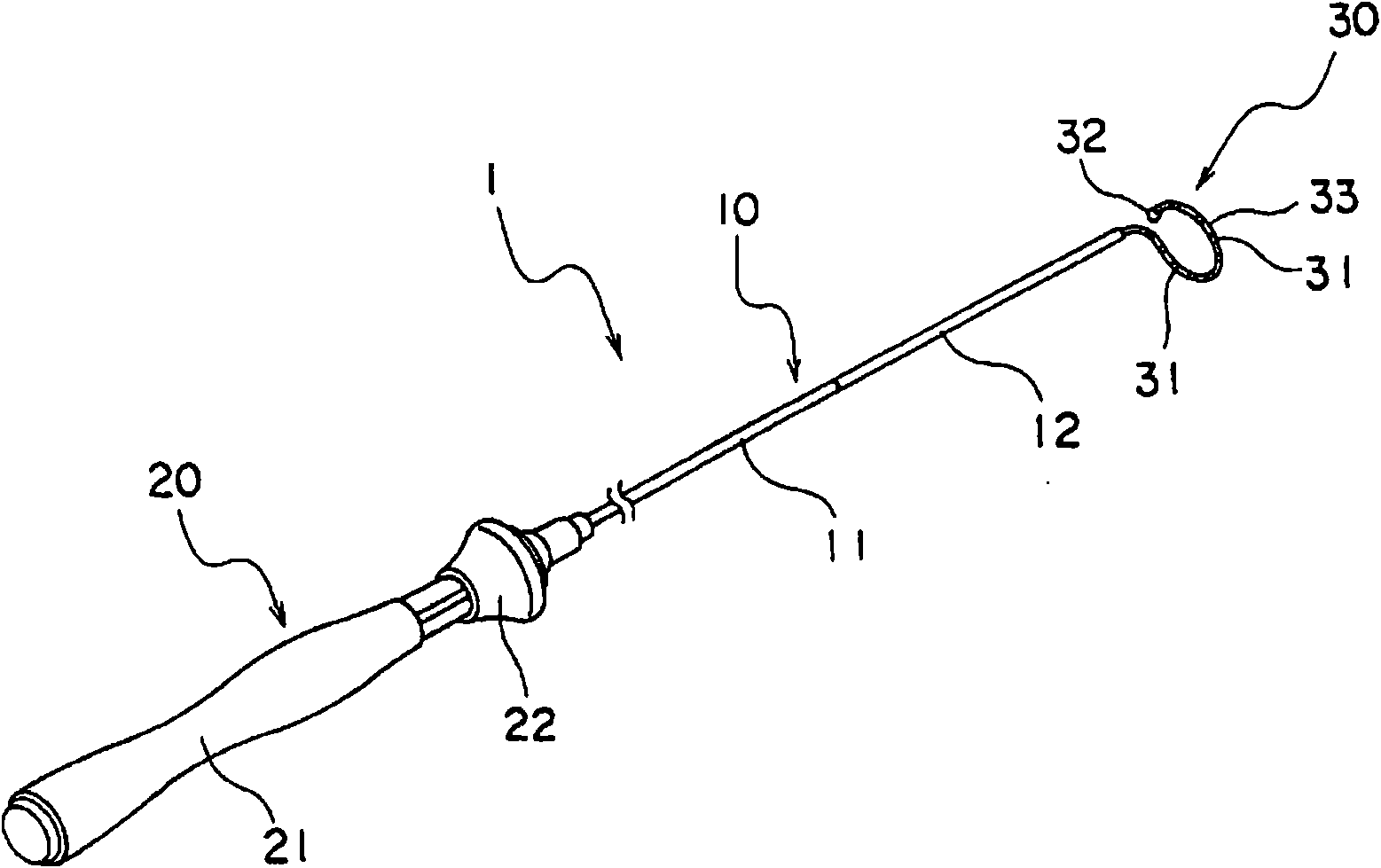
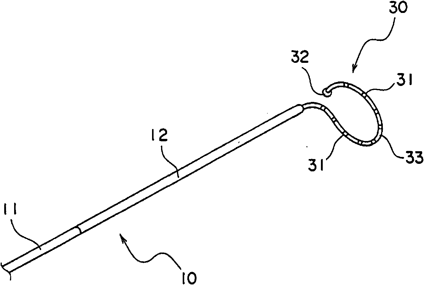
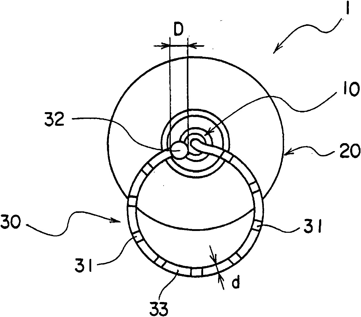
[0069] The electrode probe 1 of the present embodiment includes a probe main body 10 , a control handle 20 , and a circular ring-shaped probe tip portion 30 .

[0070] The probe main body 10 is an elongated tubular structure having an inner hole, and is composed of a first tube 11 and a second tube 12 .

[0071] The first tube 11 requires certain flexibility (bendability), incompressibility in the tube axis direction, and torsional rigidity. The rotational torque from the control handle 20 can be transmitted to the probe tip 30 by utilizing the torsional rigidity of the first tube 11 .

[0072] The first tube 11 is not particularly limited, and a tube made of resin such as polyurethane, nylon, and PEBAX (polyetherbroxamid: polyetheramide block copolymer) is braided with stainless steel wire (braided tube).

[0073] The length of the first pipe 11 is set to, for example, 50 to 200 cm.

[0074] The second tube 12 is a tube constituting the tip portion of the probe body 10, has...


PUM


Abstract

An electrode catheter comprising: a catheter body (10) having one or more inner pores; a control handle (20) connected to the base end of the catheter body (10); and a catheter tip (30) which is connected to the top end of the catheter body (10), which has an inner pore communicatively connected to at least one of the inner pores of the catheter body (10), and which is formed in a circular, loop-like shape, wherein the catheter tip (30) has two or more ring-shaped electrodes (31) attached around the rim thereof and also has a spherical chip electrode (32) attached to the end part thereof. The electrode catheter can measure a potential almost on the whole area of the catheter tip and hardly damages the inner wall of a blood vessel with the end part of the catheter tip.

Description

technical field [0001] The present invention relates to an electrode probe provided with an electrode at the tip of the probe. Background technique [0002] The beating of the heart is performed by sequentially stimulating the muscles of the heart with electrical signals that occur periodically from one part of the heart. However, when the flow of this electrical signal is abnormal, the heart cannot beat correctly. This is called heart disease. [0003] Electrode probes are known as medical devices used for diagnosing or treating irregular heartbeats. The electrode probe usually consists of a probe main body, a control handle connected to the base end side of the probe main body, and a probe front end connected to the front end side of the probe main body. ring electrode. [0004] When such an electrode probe is used to diagnose irregular heartbeats, the electrode probe is inserted into the blood vessel from the tip of the probe, and the tip of the probe is pushed to the...

Claims


Application Information

Patent Timeline
IPC IPC(8): A61B5/0408A61B5/0478A61B5/0492A61B5/296
CPCA61B5/6855A61B5/0422A61B5/287A61B5/262A61B5/6856A61B2562/0209
Inventor 长岛义昭坂野泰夫
Owner JAPAN LIFELINE CO LTD
Learn More