Frame structure system and construction method thereof

A technology of frame structure and construction method, which is applied in building components, building structure, earthquake resistance and other directions, can solve the problems of high production and construction precision requirements, large formwork laying workload, long on-site construction period and other problems, and achieves simple construction steps, The effect of small formwork laying workload and short construction time on site

Active Publication Date: 2018-07-31
江苏千禧杭萧装配式建筑科技有限公司
View PDF4 Cites 5 Cited by
  • Summary
  • Abstract
  • Description
  • Claims
  • Application Information

AI Technical Summary

Problems solved by technology

[0005] The purpose of the present invention is to provide a frame structure system and a construction method thereof, to solve the problems of heavy formwork laying workload and long construction period on site in the s

Method used


Image

  • Frame structure system and construction method thereof
  • Frame structure system and construction method thereof
  • Frame structure system and construction method thereof

Examples


Embodiment 1

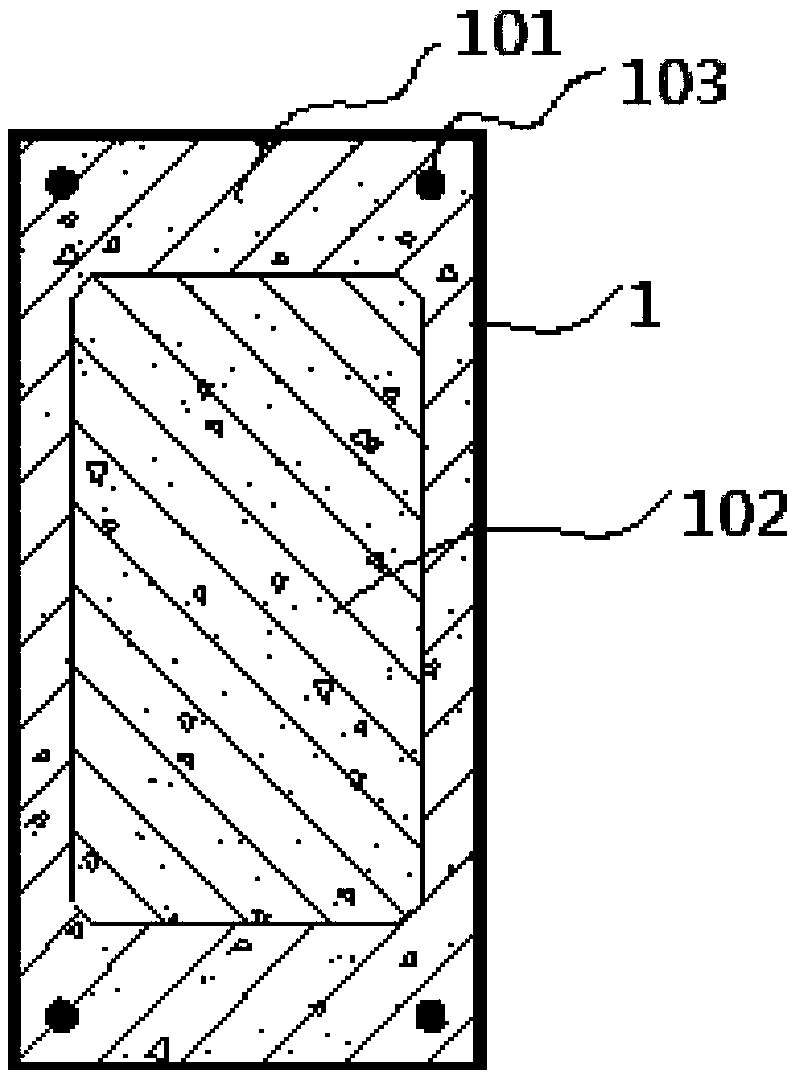
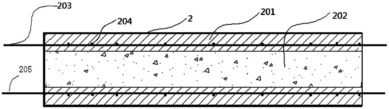
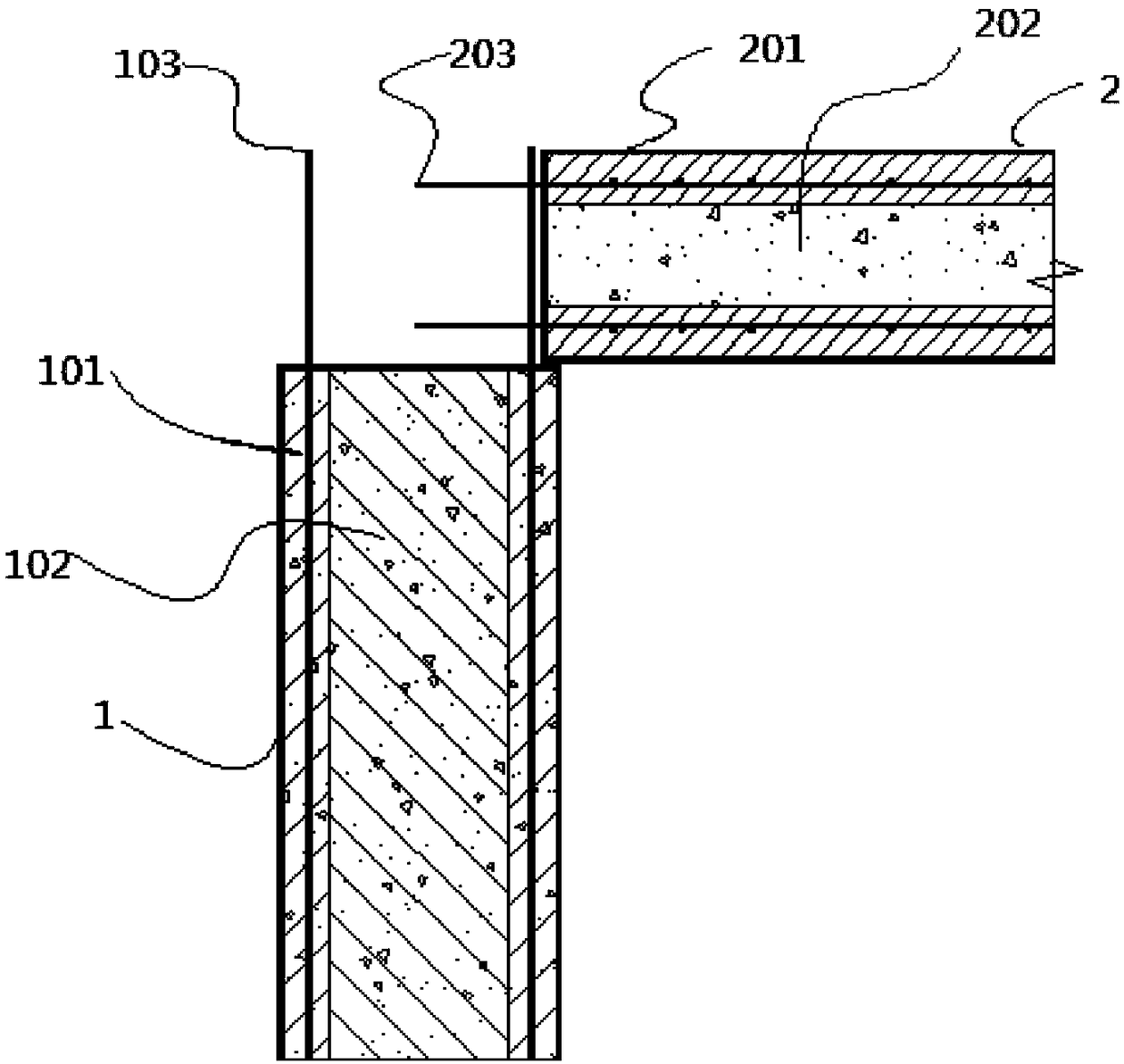
[0036] A system of frame structures comprising a plurality of beam-column joints (see attached image 3 ), beam-column joints include composite column 1 (refer to attached figure 1 ) and composite beam 2 (refer to attached figure 2), the composite column 1 includes a prefabricated column formwork 101 and a cast-in-place concrete column inner core 102, the composite beam 2 includes a prefabricated beam formwork 201 and a cast-in-place concrete beam inner core 202, and the top side of the prefabricated beam formwork 201 is provided with grouting holes and Exhaust holes (not shown in the figure), the prefabricated column formwork 101 of the composite column 1 and the prefabricated beam formwork 201 of the composite beam 2 are pre-embedded with hangers (not shown in the figure), and the prefabricated column formwork 101 Column steel bars 103 and stirrups (not shown in the figure) are provided, beam steel bars 203 and stirrups 204 are arranged in the prefabricated beam formwork 2...

Embodiment 2

[0051] The difference from Example 1 is that the beam-column joints in the frame structure system of this example include two opposite composite beams located on the same straight line, and the end of the beam reinforcement is bent parallel to the end of the column reinforcement and anchored to the beam-column in the node. Since the length of the beam reinforcement protruding from the prefabricated beam formwork and anchored in the beam-column joint is 35-40 times the diameter of the beam reinforcement, when the beam-column joint contains two opposite composite beams on the same straight line, the relative The beam reinforcement ends of the two composite beams are bent and then anchored to the beam-column joints, which can effectively solve the technical problem of insufficient accommodation space for the beam reinforcements of the two composite beams at the beam-column joints.

[0052] As an improvement of this embodiment, an elastic steel cable is provided at the node of the...

Embodiment 3

[0054] The difference from Embodiment 1 and Embodiment 2 is that a beam-column joint in the frame structure system of this embodiment includes a composite column 1 and a composite beam 2, and the cast-in-place concrete column core 102 of the composite column 1 is also made of steel fiber reinforced concrete Pouring formed. The formula of the above-mentioned steel fiber concrete is 700-800 parts of Portland cement, 120-200 parts of power plant fly ash above grade II, 80-150 parts of silicon powder of 920U and above, 900-1100 parts of quartz sand, water-reducing 40-68 parts of agent, 150-175 parts of water, 75-120 parts of steel fiber with a length of 9-12 mm, and 200-400 parts of broken ceramic chips or construction crushed waste with a particle size of 0.1-35 mm. The beneficial effects of this embodiment are as follows: 1. The whole of the composite column is steel fiber concrete, compared with the prefabricated column of ordinary concrete or only the composite column of steel...


PUM


Abstract

The invention provides a frame structure system and a construction method thereof. The frame structure system comprises a plurality of composite columns and composite beams. Each composite column comprises a prefabricated column mold shell and a cast-in-situ concrete column inner core. Each composite beam comprises a prefabricated beam mold shell and a cast-in-situ concrete beam inner core. The top side of each prefabricated beam mold shell is provided with a grouting hole and an exhaust hole. 1-20cm of the end head of each composite beam is in lap joint with the edge of the top side of the corresponding composite column. The composite beams and the composite columns are connected through cast-in-situ concrete to form beam-column joints. The end heads of beam rebars of the composite beamsextend out of the ends of prefabricated beam mold shells and are anchored in the cast-in-situ concrete of the beam-column joints. The construction method comprises the following steps that prefabricated column mold shells are hoisted to the predetermined positions; the cast-in-situ concrete beam inner cores of the composite columns are formed through grouting; the prefabricated beam mold shells are hoisted, and 1-20cm of the end heads of the prefabricated beam mold shells are in lap joint with the edges of the top sides of the prefabricated column mold shells; templates at the beam-column joints are erected; the cast-in-situ concrete beam inner cores of the composite beams are formed through grouting; the concrete at the beam-column joints is grouted; and the steps are repeated until construction of the building frame is completed.

Description

technical field [0001] The invention relates to the technical field of construction, in particular to a frame structure system and its construction method Background technique [0002] In the existing field of prefabricated buildings, there are mainly semi-prefabricated and fully prefabricated methods for beam-column joints in the frame system: [0003] (1) Semi-prefabricated method: the column is bound with on-site reinforcement and concrete is poured, the beam is a composite beam, the lower part of the composite beam is a prefabricated part, and the upper part is a cast-in-place part; the composite beam and the cast-in-place column are connected by cast-in-place concrete , forming cast-in-place beam-column joints. This kind of beam-column joint and its construction method still need to bind the column reinforcement on site, set up the column, the cast-in-place part of the composite beam and the formwork at the beam-column joint. , The on-site concrete pouring workload is...

Claims


Application Information

Patent Timeline
IPC IPC(8): E04B1/19E04B1/21E04B1/98E04H9/02
CPCE04B1/19E04B1/21E04H9/021
Inventor 何贵中
Owner 江苏千禧杭萧装配式建筑科技有限公司
Why Eureka
Try Eureka