Synchronous continuous support pulling construction method of long and large steel box girder

A construction method and technology of steel box girder, applied in bridges, bridge construction, erection/assembly of bridges, etc., can solve the problems of unsuitable long steel box girder tow erection, difficulty in erection accuracy control, and large deviation as the bridge is longer. , to achieve the effect of saving auxiliary engineering volume and cost, ensuring erection accuracy and speeding up construction progress

Active Publication Date: 2010-01-20
CHINA TIESIJU CIVIL ENG GRP CO LTD +1
View PDF0 Cites 11 Cited by
  • Summary
  • Abstract
  • Description
  • Claims
  • Application Information

AI Technical Summary

Problems solved by technology

[0004] At present, there are basically two construction methods for dragging and erecting bridges. One is that the dragging point is pulled at the front end of the bridge, and the other is that the dragging point is pushed at the end of the bridge. No matter which construction method is used, one end is a free end. , in the process of bridge erection, when there is a small deviation at the end of the drag action point, there will be a large deviation at the free end. The longer the bridge, the greater the deviation, the direction is difficult to control, and the erection accuracy is difficult to control. It is not suitable for long steel boxes. beam erection

Method used


Image

  • Synchronous continuous support pulling construction method of long and large steel box girder
  • Synchronous continuous support pulling construction method of long and large steel box girder
  • Synchronous continuous support pulling construction method of long and large steel box girder

Examples


Embodiment Construction

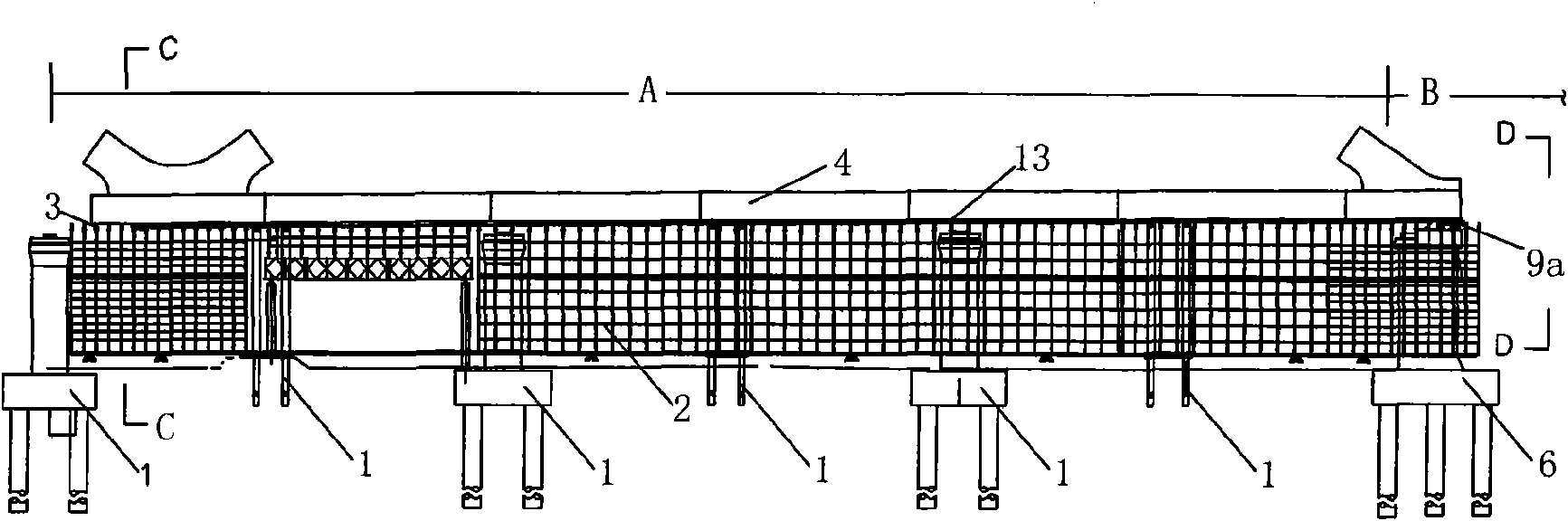
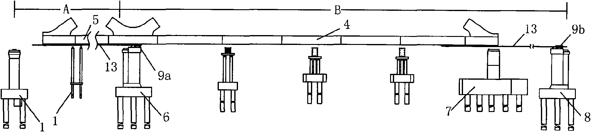
[0030] In this example, figure 1 with figure 2 The area of ​​part A shown in is the simply supported beam area, and the area of ​​part B is the steel box girder area.

[0031] The synchronous continuous jacking construction method adopted for the long steel box girder is carried out according to the following steps:

[0032] ①, figure 1 As shown, in the simply supported beam area at the end of the steel box girder area, along the center line of the steel box girder, a steel box girder assembly composed of simply supported beam area column 1, bowl buckle scaffold 2 and horizontal mold 3 is set. Support; assemble the first steel box girder 4 on the steel box girder assembly support;

[0033] ②, figure 1 , figure 2 As shown, on the No. 1 pier 6 in the steel box girder area, two No. 1 jacks 9a that can work synchronously are installed symmetrically along the center line of the bridge;

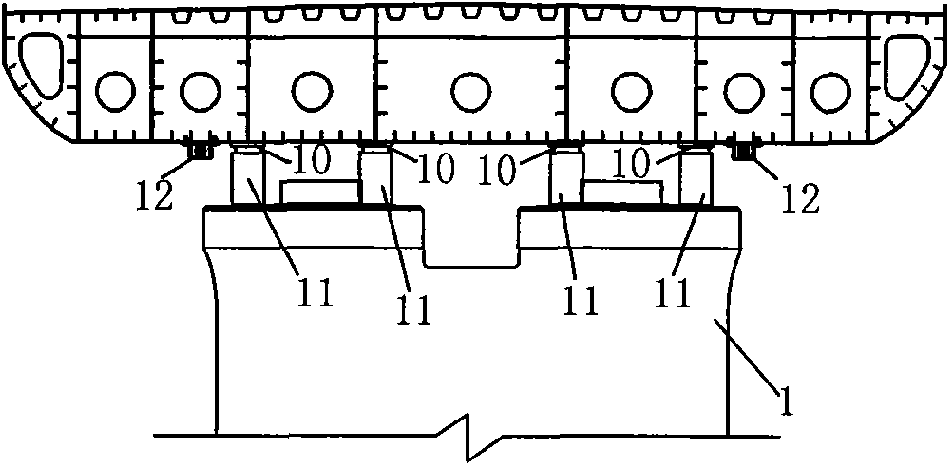
[0034] ③, image 3 , Figure 4 As shown, the slideway is set, including the upper sli...


PUM


Abstract

The invention relates to a synchronous continuous support pulling construction method of a long and large steel box girder, which is characterized by comprising the following steps: firstly, assembling a first steel box girder on a steel box girder assembling bracket of a simply supported girder area, slipping the first steel box girder on a pier I and a pier II in the steel box girder in a support pushing manner; assembling a final steel box girder continuously on the assembling bracket, and slipping the first and final steel box girders to the steel box girder area in a support pulling manner so that the first steel box girder is supported on a pier III and pier II in the steel box girder area, and the final steel box girder is supported on the pier I and pier II in the steel box girder area for construction; a support pulling system is arranged symmetrically along a central line of a bridge, and each section is symmetrically provided with two jacks arranged on the two sections for providing power to the first and final steel box girders. The method can effectively reduce offset in the hauling process of the steel box girder and ensures the installing precision of the long and large steel box girders.

Description

technical field [0001] The invention relates to a construction method for bridge erection, more specifically, a construction method applied in bridge construction, aiming at assembling and dragging the long steel box girder to the side. Background technique [0002] With the development and progress of society, bridge engineering as a scene, especially bridges located in scenic areas, urban areas or across highways, rivers and other structures, not only need to meet the use requirements, but also have good landscape effects, to achieve Harmonious and unified with the natural environment, so the bridge type has diversified, and higher requirements have been put forward for the construction. [0003] The 2-90m superimposed arch of Yandang Mountain Super Bridge, a new construction project of Yongtaiwen Railway, is located in Yandang Mountain, a national scenic spot. It is a highlight project, key project and control project of Yongtaiwen Railway. The location is across the Nin...

Claims


Application Information

Patent Timeline
Patent Type & Authority Applications(China)
IPC IPC(8): E01D21/00
Inventor 梅俊杨翼伍军熊庆华杨红卫
Owner CHINA TIESIJU CIVIL ENG GRP CO LTD
Why Eureka
Try Eureka