Reverse circulation blowing-down device of wing boundary layer

A boundary layer and wing technology, applied in wings, aircraft parts, transportation and packaging, etc., can solve the problems of inability to actively adjust the flight status, the principle of the shock blowing scheme is unknown, and the acceleration of the viscous bottom layer, etc., to achieve light weight, Low energy consumption and the effect of suppressing flow separation

Inactive Publication Date: 2010-01-27
BEIHANG UNIV
View PDF0 Cites 6 Cited by
  • Summary
  • Abstract
  • Description
  • Claims
  • Application Information

AI Technical Summary

Problems solved by technology

The passive control method has the advantage of simple structure, but at the same time there are obvious shortcomings: the passive control method can only improve the flow of a certain state point, and cannot actively adjust to deal with complex and changeable flight conditions
The advantage of this method is that it has considerable active control capability, but the disadvantage is also obvious. It needs to set a large number of sensors to determine the flow field state of each part of the wing, so that corresponding adjustments can be made
[0007] It is precisely because each active control scheme has its own shortcomings that are difficult to overcome, so the boundary layer active control technology is rarely used in actual flight. There is a big breakthrough, the blowing and suction scheme still stays on the idea of ​​accelerating the viscous bottom layer, the principle of the oscillating blowing scheme is not clear, and the essence of electromagnetic control is still the idea of ​​passive control such as changing the curvature and thickness of the wing. Trying to use advanced technology to solve the problem of boundary layer control, but limited by the current technical level, it is still difficult to be effective in real flight

Method used


Image

  • Reverse circulation blowing-down device of wing boundary layer
  • Reverse circulation blowing-down device of wing boundary layer
  • Reverse circulation blowing-down device of wing boundary layer

Examples


Embodiment Construction

[0037] The present invention will be further described in detail with reference to the accompanying drawings and embodiments.

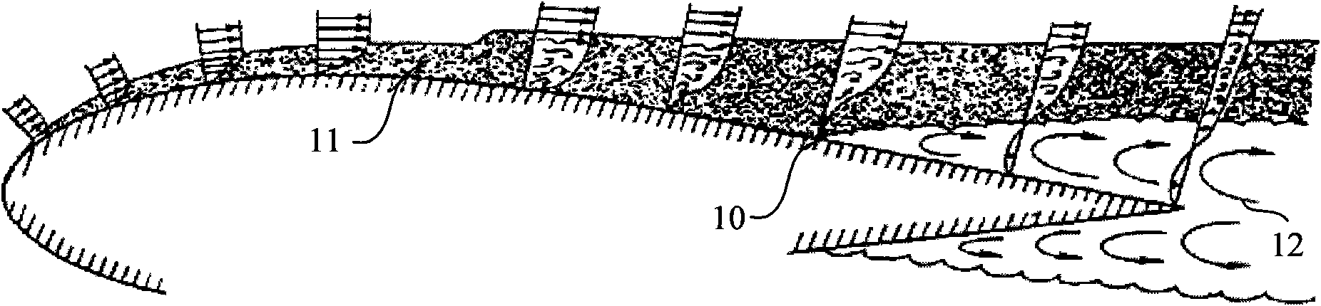
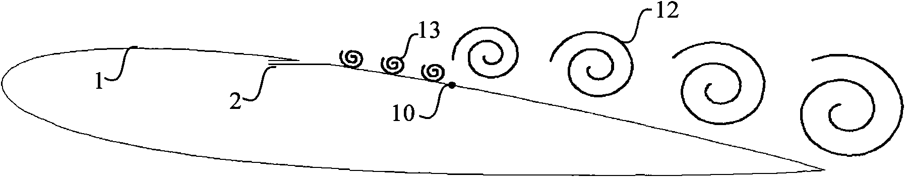
[0038] Such as figure 2 As shown, after the separation point 10 on the wing 1, a clockwise-rotating separation vortex 12 has occurred, and the present invention produces a counterclockwise vortex 13 opposite to the separation vortex 12 at the blowing slot 2 of the wing 1, and uses the counterclockwise vortex 13 to weaken and counteract the flow separation vortex 12; at the same time, the high-speed airflow blown out also increases the flow velocity of the bottom layer, and the two are used together to better eliminate flow separation.

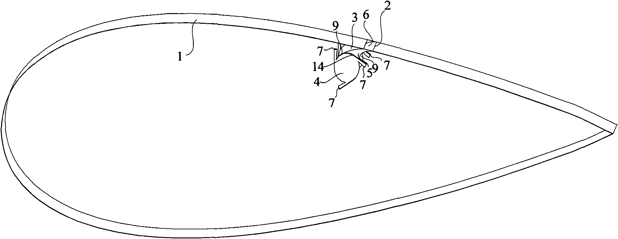
[0039] The present invention is a kind of airfoil boundary layer anti-circulation amount blowing device, such as image 3 , Figure 4 As shown, it includes blowing channel 3 , cyclone 4 and sealing connection platform 5 .

[0040] Have blowing slot 2 on the surface of wing 1, described blowing slot 2 is positioned ...


PUM


Abstract

The invention discloses a reverse circulation blowing-down device of a wing boundary layer, comprising a blowing passage, whirlcones and an end surface, wherein wing surfaces are provided with blowing slits, the blowing passage is in the shape of a curved surface and comprises a circular arc surface and a curved surface, wherein one end of the curved surface is smoothly connected with the circular arc surface, the other end of the curved surface is connected with the blowing slits and is tangent with the wing surfaces, and the tangent positions are processed with chamferings; the blowing passage is perpendicular to both ends of the plane of wings or the middle of the blowing passage is connected with the whirlcones, and the radius and the wall thickness of the circular arc surface are equal to that of circular cavities of the whirlcones; the whirlcones positioned on both ends of the blowing passage are sealed with the surfaces and the curved surfaces of the wings by the end surface and are provided with tangential air inlets, and the air flow rotating directions of the whirlcones are reverse to a bypass flow whirlpool. Compared with a common independent blowing scheme, the reverse circulation blowing device of the wing boundary layer better restrains the flow separation, can thoroughly eliminate the separation areas under small blowing quantity and enhance the flow field quality.

Description

technical field [0001] The invention relates to an airfoil boundary layer anti-circulation blowing device, which belongs to the technical field of fluid flow separation control. Background technique [0002] Boundary layer separation is a flow separation phenomenon in which the boundary layer separates from the surface of an object due to the existence of viscosity. This phenomenon seriously restricts the development of human aviation, aerospace, navigation and other related fields of fluid mechanics. For aircraft, both its shape design and engine compressor design are adversely affected by boundary layer flow separation phenomena such as aircraft stall and engine surge. The research on boundary layer flow control technology started almost as early as 1904 when Prandtl put forward the boundary layer (also known as boundary layer) theory, and made some progress. [0003] Such as figure 1 Shown is a schematic diagram of boundary layer flow separation on the airfoil surface. ...

Claims


Application Information

Patent Timeline
Patent Type & Authority Applications(China)
IPC IPC(8): B64C3/00B64C3/36B64C3/28
Inventor 高歌王林林
Owner BEIHANG UNIV
Why Eureka
Try Eureka