
Radial expansion type punch

A technology of radial expansion and punch, applied in metal processing equipment, perforation tools, manufacturing tools, etc., can solve the problems of low grinding efficiency, low efficiency and long production cycle by grinding method, so as to improve labor productivity, The effect of reducing manufacturing cost and shortening production cycle

Active Publication Date: 2010-02-03
SHANGHAI ZHUGUANG MACHINERY +1
View PDF0 Cites 4 Cited by
  • Summary
  • Abstract
  • Description
  • Claims
  • Application Information

AI Technical Summary

Problems solved by technology

[0004] The split punching method puts the main punch in advance at the welding seam, which has great potential safety hazards;
[0005] The grinding efficiency of the grinding method is low
[0006] The above three methods need to adopt secondary heat treatment, the production cycle is long, the efficiency is low, the cost is high, and the safety is poor, so it is not suitable for large-scale production

Method used


Image

  • Radial expansion type punch
  • Radial expansion type punch
  • Radial expansion type punch

Examples


Embodiment Construction

[0022] Next, preferred embodiments of the radially expandable punch of the present invention will be described with reference to the accompanying drawings.

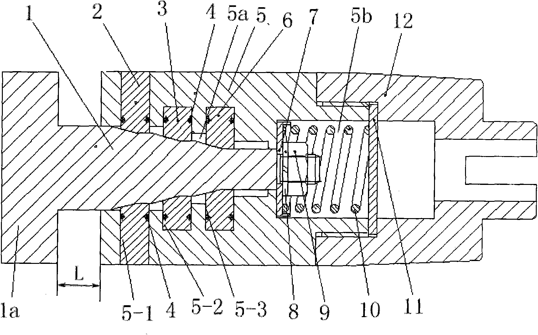
[0023] like figure 1 As shown, the radial expansion punch of the present invention has a T-shaped front punch 1 , a first layer of cutter blocks 2 , a second layer of cutter blocks 3 , a third layer of cutter blocks 6 and a cutter block seat 5 .

[0024] The inside of the knife block seat 5 has two spaces 5a, 5b with open ends separated by an inner flange (not shown). The outer peripheral surface of the knife block seat 5 is provided with a total of three groups of knife block radial expansion slots 5-1, 5-2, 5- 3.

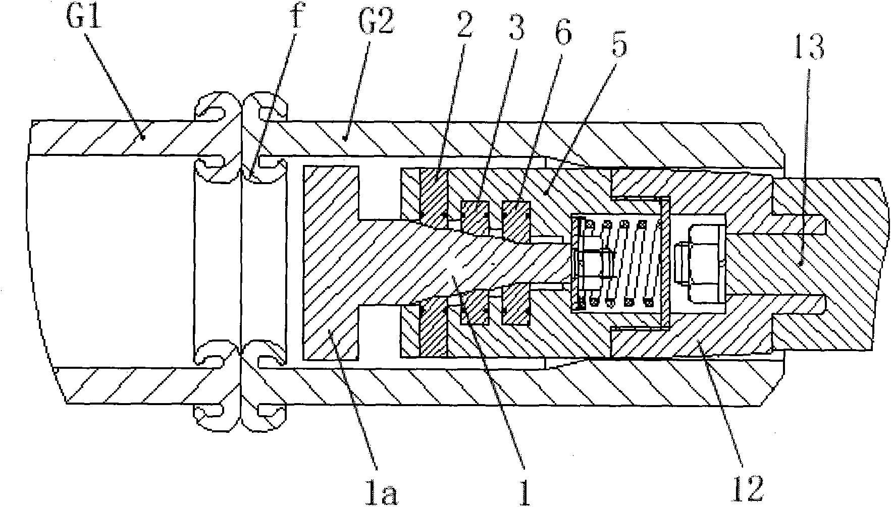
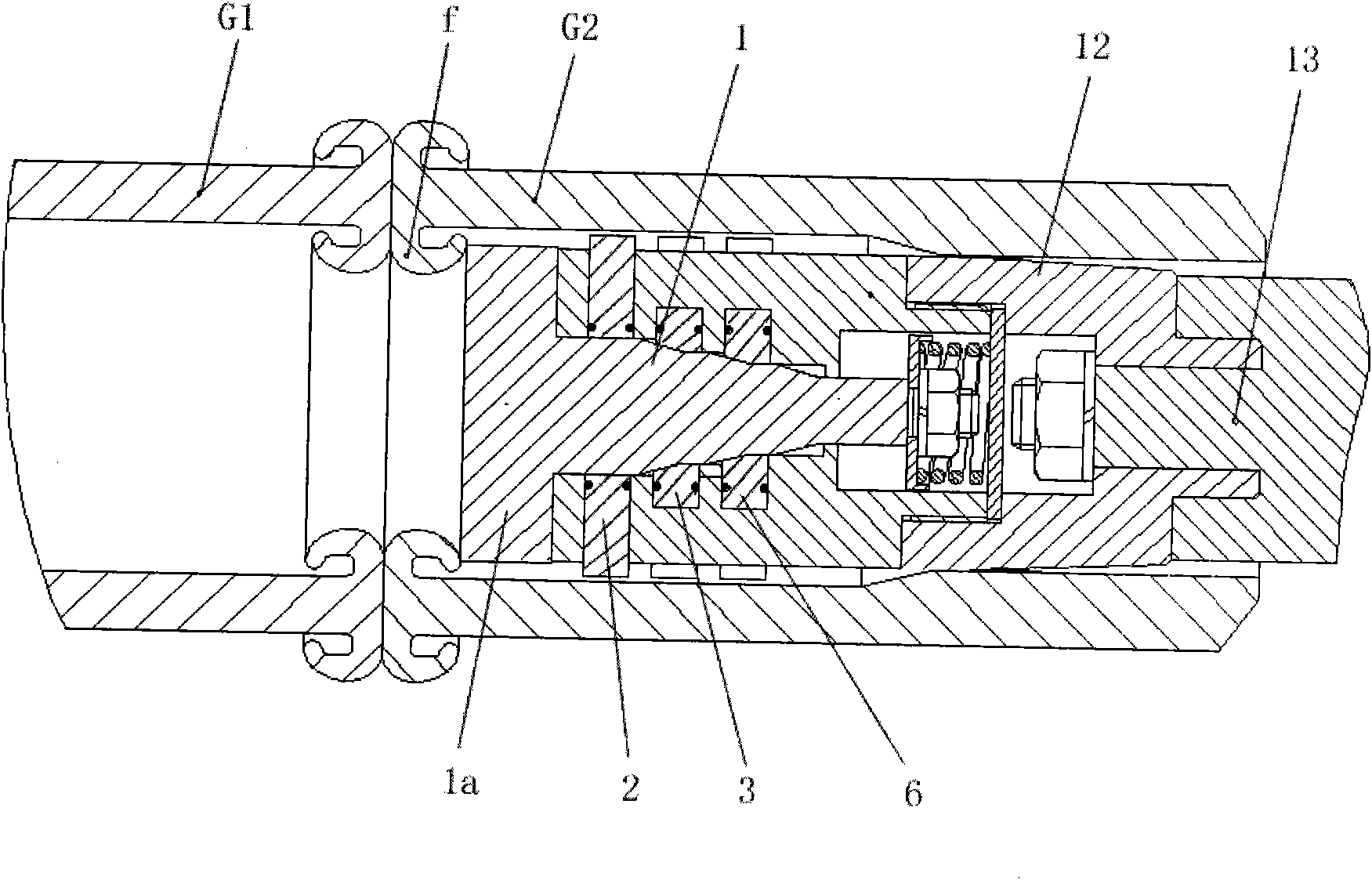
[0025] The shaft body of the T-shaped front punch 1 in a space 5a in two spaces 5a, 5b has a certain taper (refer to figure 1 or figure 2 , 3 As shown, in a preferred embodiment of the present invention, the taper is set to 30 degrees (that is, the inclined plane is 15 degrees) to form a large stepped s...


PUM


Abstract

The invention relates to a radial expansion type punch, which is provided with a front punch (1), a first layer knife block, a second layer knife block, a third layer knife block (2, 3, 6) and a knifeblock base (5), wherein the knife block base is provided with two spaces (5a, 5b) inside; the peripheral surface of the knife block base in the same space is provided with three groups of knife blockradial expansion grooves (5-1, 5-2, 5-3); a shaft body of the front punch consists of a large stepped shaft, a medium stepped shaft and a small stepped shaft with certain tapers respectively; all thelayer knife blocks are arranged on the stepped shafts in sequence through the three groups of radial knife block radial expansion grooves respectively; the shaft end of the front punch passes througha washer (7) and is arranged in the other space; the other space is sealed by a retaining ring (11), and the sealed space is provided with a compression spring (10) inside; and all the layer knife blocks are provided with a tension spring (4) respectively. The radial expansion type punch is simple in structure, can avoid secondary welding line heat treatment and reduce production cost, and is suitable for large-scale drill pipes or two-pipe combined production lines.

Description

technical field [0001] The invention relates to a metal punching device, in particular to a radially expanding punch belonging to a cutter. Background technique [0002] In the production process of the drill pipe or the combination of the two reducing pipes, the drill pipe joint and the drill pipe body or the pipe body between the two reducing pipes are connected by the friction welding method, and the weld seam after friction welding There will be flash on the inner and outer walls. Due to the different hole diameters on the inner wall of the pipe, special processing methods must be used to remove the flash and make the inner cavity clean and smooth. Therefore, removing flash is an important key process. The traditional methods of removing flash include straight hole punching method, split punching method and grinding method. [0003] The straight hole punching method requires secondary heat treatment, and the production cycle is long; [0004] The split punching metho...

Claims


Application Information

Patent Timeline
IPC IPC(8): B21D28/14B21D28/34
Inventor 金文达袁世根
Owner SHANGHAI ZHUGUANG MACHINERY
Features
  • Generate Ideas
  • Intellectual Property
  • Life Sciences
  • Materials
  • Tech Scout
  • Unparalleled Data Quality
  • Higher Quality Content
  • 60% Fewer Hallucinations
Learn More