
Optical fiber acceleration transducer

An acceleration sensor and acceleration technology, applied in the direction of acceleration measurement using inertial force, can solve the problems of low measurement accuracy, poor environmental adaptability, and high cost, and achieve the effects of strong anti-interference ability, wide response frequency band, and high sensitivity

Inactive Publication Date: 2010-02-03
SHENZHEN UNIV
View PDF0 Cites 26 Cited by
  • Summary
  • Abstract
  • Description
  • Claims
  • Application Information

AI Technical Summary

Problems solved by technology

However, the sensors made by this principle are generally complex in structure, need to be powered on, and have poor environmental adaptability and are susceptible to electromagnetic interference.
There is also the use of optical fiber sensing technology to measure acceleration, but it is generally limited to using optical fiber as the optical transmission medium, and the sensor structure is generally too complicated, the cost is high, the measurement accuracy is low, and remote measurement cannot be realized

Method used


Image

  • Optical fiber acceleration transducer
  • Optical fiber acceleration transducer
  • Optical fiber acceleration transducer

Examples


Embodiment Construction

[0020] The preferred embodiments of the present invention will be described in detail below in conjunction with the accompanying drawings.

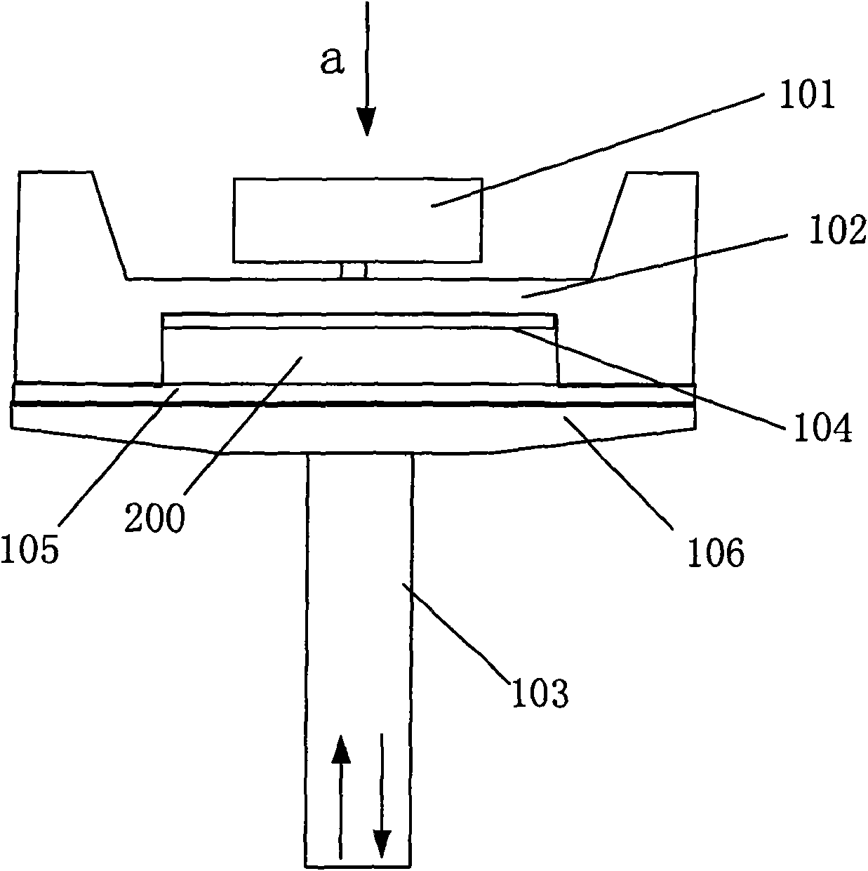
[0021] Optical fiber acceleration sensor of the present invention is based on Fabry-Perot (Fabry-Perot, F-P) interference principle, and its structure is as follows figure 1 As shown, it includes an optical fiber 103 and an elastic diaphragm 102, wherein the end face of the optical fiber 103 and the elastic diaphragm 102 are parallel to each other to form a Fabry-Perot cavity (F-P cavity) 200, which uses multi-beam interference to detect the acceleration of the measured object.

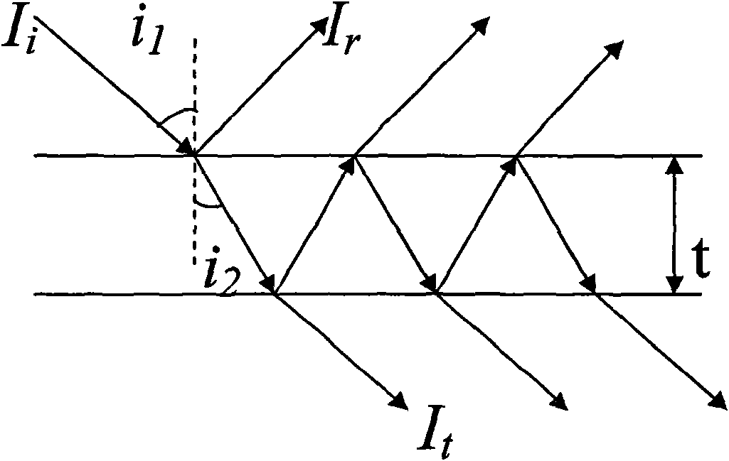
[0022] The schematic diagram of the principle of multi-beam interference is as follows: figure 2 As shown, when the monochromatic light I i When it is incident on a flat plate whose upper and lower surfaces are parallel, reflection and refraction will occur on both the upper and lower surfaces of the plate, and the incident angle i 1 ≈0, i.e. close to normal i...


PUM


Abstract

The invention discloses an optical fiber acceleration transducer comprising an optical fiber and an elastic membrane. The end surface of the optical fiber and the elastic membrane are arranged in parallel to form an Fabry-Perot cavity; a mass block is arranged on the elastic membrane for generating inertia force under the action of the acceleration of an object to be measured, and the inertia force acts on the elastic membrane so that the length of the Fabry-Perot cavity varies with the acceleration of the object to be measured, and a varied interference spectrum is transferred by the opticalfiber. The optical fiber acceleration transducer has minor size, strong capacity of resisting disturbance, wide response bandwidth, high sensitivity and low cost and can be widely applied to acceleration measurement.

Description

technical field [0001] The invention relates to the technical field of optical fiber sensing, in particular to an optical fiber acceleration sensor. Background technique [0002] Optical fiber sensing technology is a new type of sensing technology developed rapidly with the development of optical fiber communication technology in the 1970s. It can be used to measure various physical quantities, such as sound field, electric field, pressure, temperature, angular velocity, acceleration, etc. It can also be completed Measurement tasks that are difficult to complete with existing measurement technologies. In the environment of strong electromagnetic interference and high voltage, fiber optic sensors have shown unique capabilities. [0003] Acceleration is an important parameter to be measured for safety status monitoring in many fields such as industry. The measurement of the acceleration signal usually uses the principle of inertia to measure the corresponding acceleration by...

Claims


Application Information

Patent Timeline
IPC IPC(8): G01P15/03
Inventor 李学金邓元龙
Owner SHENZHEN UNIV
Learn More