Cage-locking, cage-stabilizing and overwinding and overfalling brake device for of skip of cage of vertical shaft

A braking device and cage technology, which is applied in hoisting devices, transportation and packaging, lifting equipment in mines, etc., can solve the problems of large up and down movement, and achieve the effect of convenient installation and debugging, and simple structure

Inactive Publication Date: 2010-02-10
李萌
View PDF0 Cites 4 Cited by
  • Summary
  • Abstract
  • Description
  • Claims
  • Application Information

AI Technical Summary

Problems solved by technology

[0013] The technical problem to be solved by the present invention is to overcome the technical defects of the prior art. In order to solve the problem of large up and down movement of the cage when loading deep wells and heavy equipment lifting tasks and the shortcomings of the existing over-rolling and over-releasing devices, the present invention Provide shaft cage skip lock tank stabilizer and over-rolling and over-discharging braking device. When loading and unloading, the device locks the cage at the normal parking level position, avoiding the sudden up and down movement of the cage due to the elastic change of the steel wire rope during loading and unloading, ensuring stable loading and unloading When the loading and unloading is completed, the device releases the brake slowly, and the cage rises or falls steadily

Method used


Image

  • Cage-locking, cage-stabilizing and overwinding and overfalling brake device for of skip of cage of vertical shaft
  • Cage-locking, cage-stabilizing and overwinding and overfalling brake device for of skip of cage of vertical shaft
  • Cage-locking, cage-stabilizing and overwinding and overfalling brake device for of skip of cage of vertical shaft

Examples


Embodiment Construction

[0021] The present invention will be described in further detail below in conjunction with the accompanying drawings and embodiments.

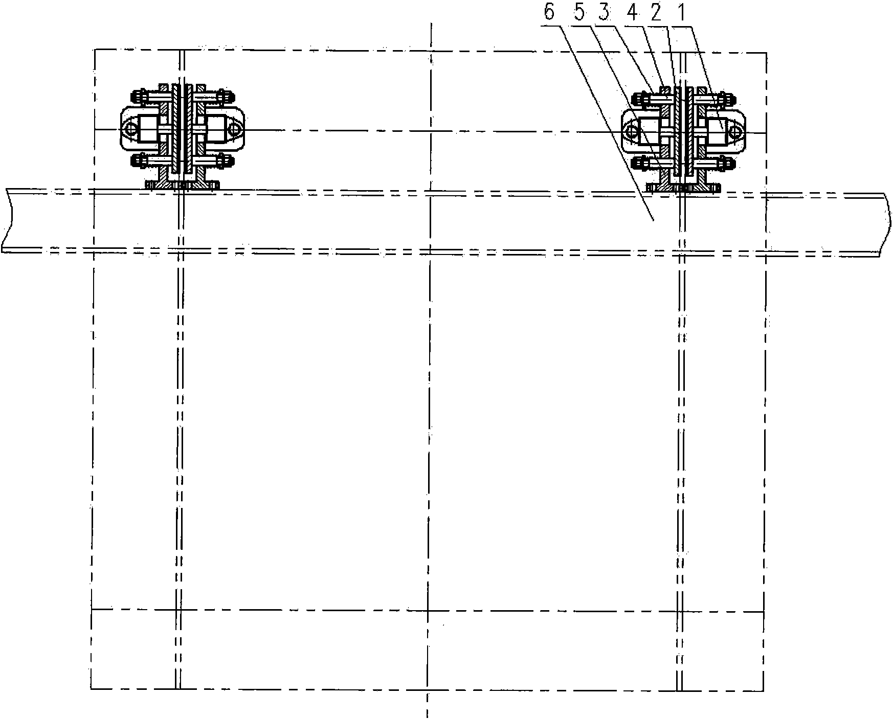
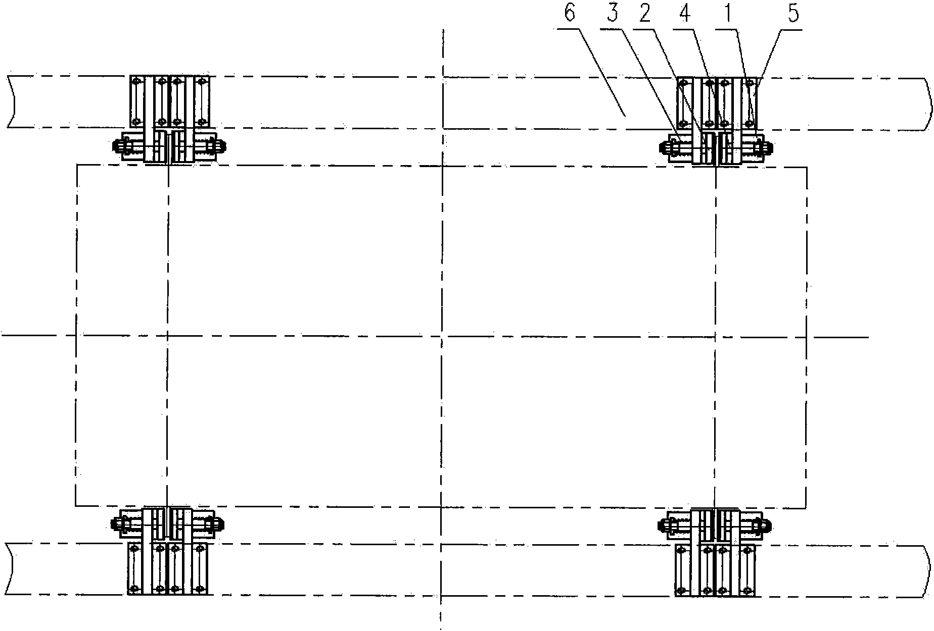
[0022] Vertical well cage skip lock tank stabilizer and over-rolling and over-discharging brake device, which consists of brake cylinder (1), brake plate and friction lining (2) brake release spring (3) bearing pin (4) support (5 ), installation beam (6), hydraulic servo system and electric control system (7). It is characterized in that: the brake plate is installed on the lifting container, the width of the brake plate is 180mm, the thickness is greater than 30mm, and the length is the same as the height of the lifting container. The brake cylinder (1) is installed on the support (5) with a pin shaft; the brake plate and friction lining (2) brake release spring (3) bearing pin (4) are installed on the support (5); The seat (5) is connected to the mounting beam (6) by welding or bolts. The device is normally open, with hydraulic cylinders t...


PUM


Abstract

The invention discloses a cage-locking, cage-stabilizing and overwinding and overfalling brake device of a skip of a cage of a vertical shaft. The brake device consists of a brake oil cylinder (1), abrake plate and friction lining (2), a brake-releasing spring (3), a bearing pin (4), a supporting seat (5), a mounting beam (6), and a hydraulic servo system and electric control system (7). The brake device is characterized in that: the brake oil cylinder (1) is arranged on the supporting seat (5) by a pin shaft; the brake plate and friction lining (2), the brake-releasing spring (3) and the bearing pin(4) are arranged on the supporting seat(5); and the supporting seat (5) is in welding connection or bolted connection with the mounting beam (6). Due to the adoption of the structure of the bearing pin, the brake oil cylinder is not the directly operated type, and the braking force is not transferred to a piston, so that the oil leakage problem (the prior hydraulic disc type brake is the directly operated type, and the braking force is directly transferred to the piston.) is thoroughly solved. The operating principle of the brake device comprises that: when the cage stops at the mouthor bottom of a mine, the brake oil cylinder drives the brake plate and friction lining to clip the brake plate of the cage, so that the cage is stabilized by the friction force; and when the cage or skip is overwound or overfallen, the brake oil cylinder can clip the brake block in a mode of changing pressure, so that the cage or skip can be braked in the overwinding or overfalling range, and thebraking force meets the requirements of mine safety rules.

Description

Technical field [0001] The invention is a safety device in a mine shaft hoisting system, and relates to a locking and stabilizing tank used for hoisting a mine shaft cage, preventing the cage from moving up and down during loading and unloading, and braking after the cage is overwound and unloaded And braking device, especially suitable for use in deep shaft and heavy equipment vertical shaft cage lifting, this device can effectively prevent the hoisting container from over-rolling and over-discharging. Background technique [0002] Currently commonly used cage receiving devices in vertical shaft cage lifting include cradle, tank supporting machine, automatic compensation tank cradle, conversion platform (foreign product), a tank locking mechanism and tank stabilizing device for vertical shaft cage lifting. [0003] The tank supporting machine has a large adjustment distance, which can be used in deep wells and large wells, and is specially used for multi-rope hoists, but it...

Claims


Application Information

Patent Timeline
IPC IPC(8): B66B17/16B66B5/08B66B5/16B66D1/56
Inventor 李萌
Owner 李萌
Why Eureka
Try Eureka