Blade pitch changing device of wind power generation device

A wind power generation device and pitch pitch technology, applied in wind power generation, wind turbine, wind turbine control, etc., can solve the problems of difficulty in maintaining the consistency of reliability and synchronization accuracy, many moving parts, and high probability of failure, etc. Achieve the effects of quickly adapting to complex wind changes, simplifying the blade pitch device, and reducing the cumulative error of node gaps

Inactive Publication Date: 2010-02-10
YIXING HUATAI INT GRP IND
View PDF9 Cites 7 Cited by
  • Summary
  • Abstract
  • Description
  • Claims
  • Application Information

AI Technical Summary

Problems solved by technology

The main disadvantages of this form of changing the blade angle by driving the small gear and meshing the large gear are: first, the volume is enlarged, and the diameter of the megawatt-level large gear is 1.2-1.8 meters, and the weight is heavy, such as a 1.5-megawatt three-blade pitch changer The torque mechanism weighs about 6 tons, which not only increases the cost, but also increases the weight of the wind power generation device and makes it difficult to manufacture; second, it is objectively very difficult to keep the deflection angle of each blade the same by controlling the motor by an electrical appliance. , it will cause vibration due to the different aerodynamic force of each blade; the third is that the structure of the angle adjustment mechanism is complex, the structure chain is long, and there are many parts. It is composed of 4 major components such as planetary reducer and motor, and there are 12 major components in three blades. It is difficult to maintain the reliability and synchronization accuracy of multiple components, and it is very difficult to lubricate and maintain high-altitude gears. As long as one component appears If there is a failure, it will not work, and the probability of failure is high; the installation of the four blades and the adjustment of the consistency of the starting angle are quite complicated, which increases the difficulty of installation and debugging
They are all just self-adjusting constant speed devices, and the centrifugal drive of heavy balls can only be used for small-power wind power generation devices, not for megawatt-level wind power generation devices. The movement of large heavy balls consumes part of the energy, which will affect power generation efficiency; secondly, the speed regulating device has many structures and moving parts, and the reliability is not high; especially the pitch adjusting device cannot be used for safe shutdown protection in high-speed wind
[0006] The pitch-changing devices disclosed in Chinese patents CN2320815 and CN1752440 adopt spring speed regulation, which still belong to centrifugal constant speed. quick effect
[0009] The pitch adjustment mechanism disclosed in Chinese patent CN200955472 still adopts a large gear rotation structure, and the component parts are much larger than the gear transmission, and the failure rate must be higher than that of the large gear; the hydraulic cylinder drives the lever mechanism, drives the rack, and drives the gear. And the lever mechanism is composed of a center wheel, a link, three levers and a bracket. There are many movable connection points and moving parts, which will inevitably lead to a decrease in precision; for high-power wind power generation, due to the large distance between the blades, the lever is within a large length. Bending force transmission, in order to ensure sufficient rigidity, the section requirements of components are very large, which increases the difficulty of weight and structural design
Multi-stage tooth meshing not only makes it difficult to lubricate at high altitudes, but also causes large wear and tear on the teeth. In addition, there are many moving parts, which not only makes it difficult to guarantee accuracy, but also has low reliability; Difficult to adapt when changes are complex
[0012] Therefore, although there are many kinds of pitch-adjusting devices in the prior art, those that can be used for megawatts have large weight, poor angle adjustment consistency, complicated manufacture, and high cost; those with relatively good angle adjustment consistency cannot be used for large megawatts. Watt level; and there are many components and moving parts, complex structure, poor reliability, large cumulative error, and low precision.

Method used


Image

  • Blade pitch changing device of wind power generation device
  • Blade pitch changing device of wind power generation device
  • Blade pitch changing device of wind power generation device

Examples


Embodiment 1

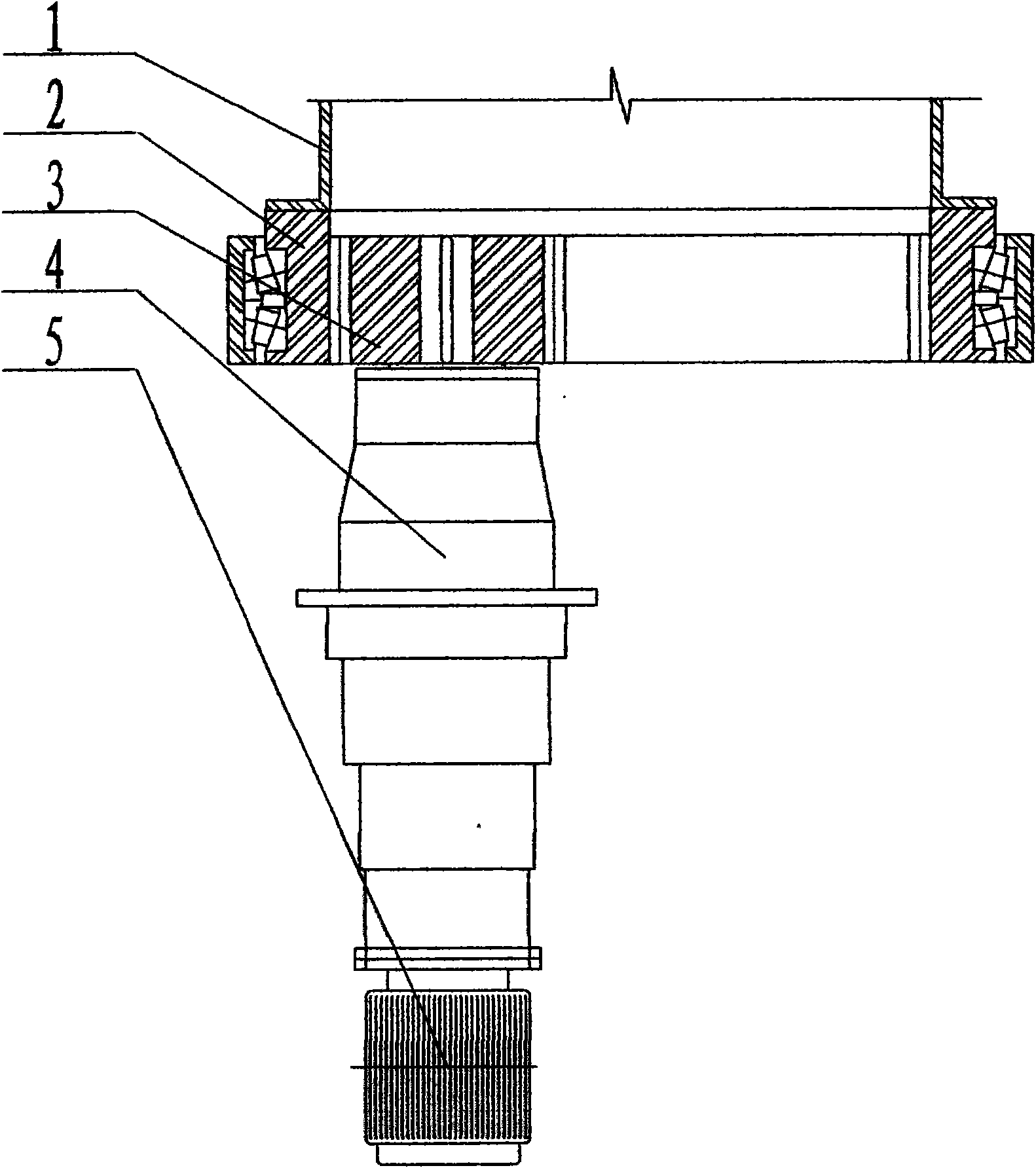
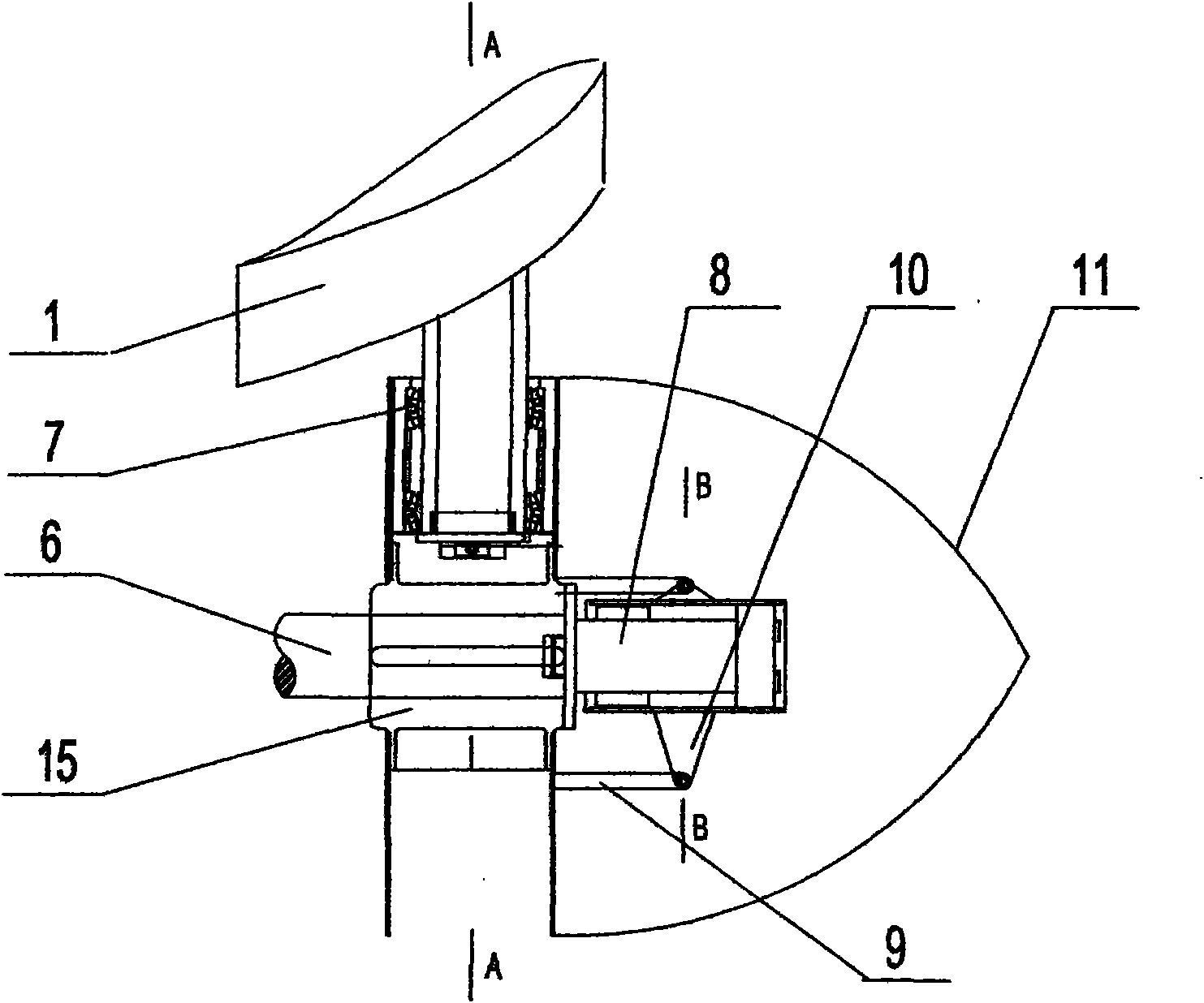
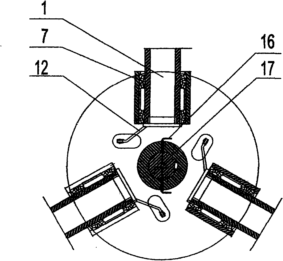
[0029] Embodiment 1: see Figure 2-6 , the piston rod of the oil cylinder 8 is fixed on the main shaft 6, so that the oil cylinder rotates with the main shaft. Each paddle 1 petiole root is fixed with a rocker bar 12, and the other end of the rocker bar is movably connected with a pull bar 9 parallel to the main shaft, and the two form a two-force bar link mechanism that drives the blade to rotate. There are left and right threaded joint bearings 13.1 and 13.2 at both ends of the tie rod 9, so that the axial length of the tie rod can be adjusted. After adjusting the length, use the nut and tighten it so that the axial length does not change again. The two joint bearings are respectively connected with the rocker arm rod 12 is flexibly connected with cylinder liner radially stretching out support arm 10. A shaft sleeve 15 is radially positioned on the main shaft 6 through a key, flange rings are provided at both ends of the shaft sleeve, on which are fixed parallel paddle moun...

Embodiment 2

[0031] Embodiment 2: As in Embodiment 1, a displacement sensor is provided on the hydraulic cylinder to detect and respond to the axial telescopic movement distance of the cylinder, and the detection data signal of the displacement sensor is output through the electric ring / brush.

Embodiment 3

[0032] Embodiment 3: see Figure 7 , as in embodiment 1, the paddle blade 1 wind wheel is arranged on the hollow shaft section 22, and the front section of the hollow shaft section 22 has an axially slidable sleeve 20 which is radially positioned by a linear bearing and a key. The radially extending support arms 18 (the embodiment is three) with the same distribution angle, between the radially extending supporting arms and the fixed rocker arm member 12 at the root of the paddle petiole, there are two ends that are movably connected (such as joint bearings) The pull rod 19, when the sleeve 20 moves axially, pulls the blade to deflect to adjust the angle of the blade. The axially moving telescopic power mechanism (for example, hydraulic cylinder 8) that drives the slurry adjustment is arranged at the rear of the wind wheel, fixed on the wind turbine support platform (fixed positioning), and the inner core (piston rod) extension rod 23 passes through The hollow shaft section o...


PUM


Abstract

The invention relates to the improvement of a blade pitch changing device of a wind power generation device, which is characterized in that a blade angle deflection driving mechanism consists of rocker bar members, pull rods and an axially telescopic power mechanism, wherein the rocker bar member is fixed on each blade shaft, the pull rods drive the rocker bar members to rotate, the axially telescopic power mechanism drives each pull rod to synchronously and axially move, and both ends of each pill rod are respectively connected with a rocker and a movable axially telescopic mechanism throughmovable pivots. The blade pitch changing device has the biggest characteristics that the blade pitch changing device is greatly simplified, the weight is greatly lightened, the megawatt-level weight is less than one fifth of the weight in a gear type, the reliability and the angle modulation consistency are good, and the blades are simply installed and adjusted, thereby being completely used for adjusting the blade pitch of a megawatt-level wind power generation device.

Description

technical field [0001] The present invention relates to the improvement of the blade pitch change device of the wind power generation device, in particular to a blade pitch change device with simple structure, easy manufacture, light weight, consistent angle adjustment and good synchronization of each blade. Background technique [0002] Horizontal axis wind turbines, objectively, often change due to the wind in the air, such as large or small changes in wind, and gust impacts, etc., which can easily cause unstable speed, which in turn causes fluctuations in the speed of the generator connected to it, seriously affecting power generation Quality and requirements, especially the power generation voltage and frequency, so it is necessary to adjust the windward angle of the blades as the wind changes. By changing the windward angle of the blades, the blade speed is kept relatively stable to ensure that the generator works within the design rated speed range. Secondly, in order ...

Claims


Application Information

Patent Timeline
Patent Type & Authority Applications(China)
IPC IPC(8): F03D7/04
CPCY02E10/723Y02E10/72
Inventor 陈忠良顾礼帮黄兵
Owner YIXING HUATAI INT GRP IND
Why Eureka
Try Eureka