Vacuum compound heat insulating pipe

A technology of vacuum heat insulation and heat insulation pipe, applied in the direction of protecting pipelines, drilling pipes, casings through heat insulation, etc., can solve the problems of short heat insulation life, long-term maintenance, difficult vacuum degree, etc. The effect of easy processing, convenient replacement and reduced maintenance cost

Active Publication Date: 2010-02-10
湖北贵族真空科技股份有限公司
View PDF5 Cites 26 Cited by
  • Summary
  • Abstract
  • Description
  • Claims
  • Application Information

AI Technical Summary

Problems solved by technology

In this patent, there are many connecting parts between the heat shields. The inner and outer pipes are made of carbon steel, which is easy to deflate under ...

Method used


Image

  • Vacuum compound heat insulating pipe
  • Vacuum compound heat insulating pipe
  • Vacuum compound heat insulating pipe

Examples


Embodiment 1

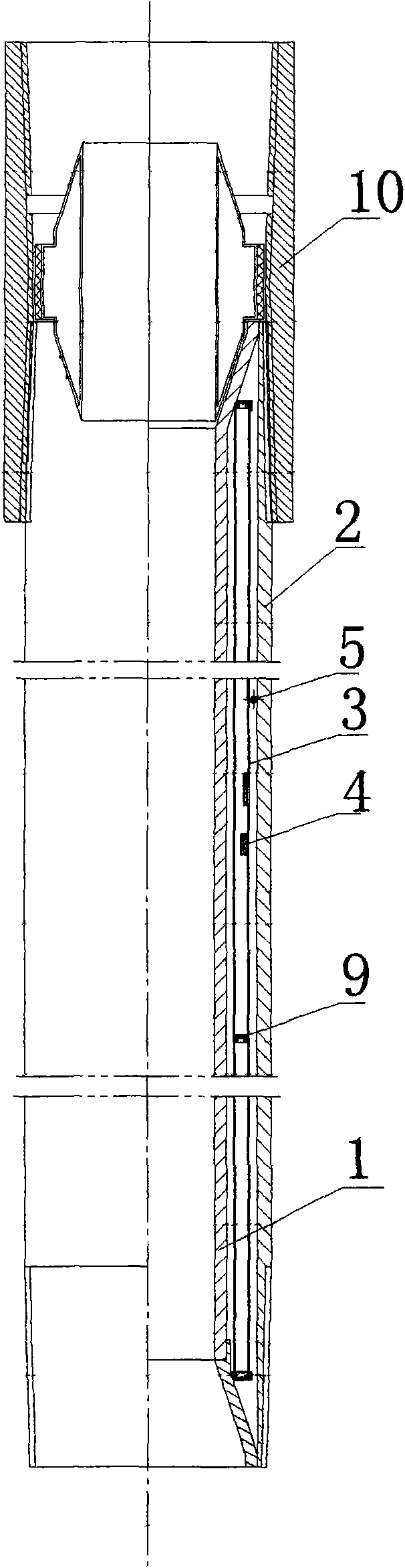
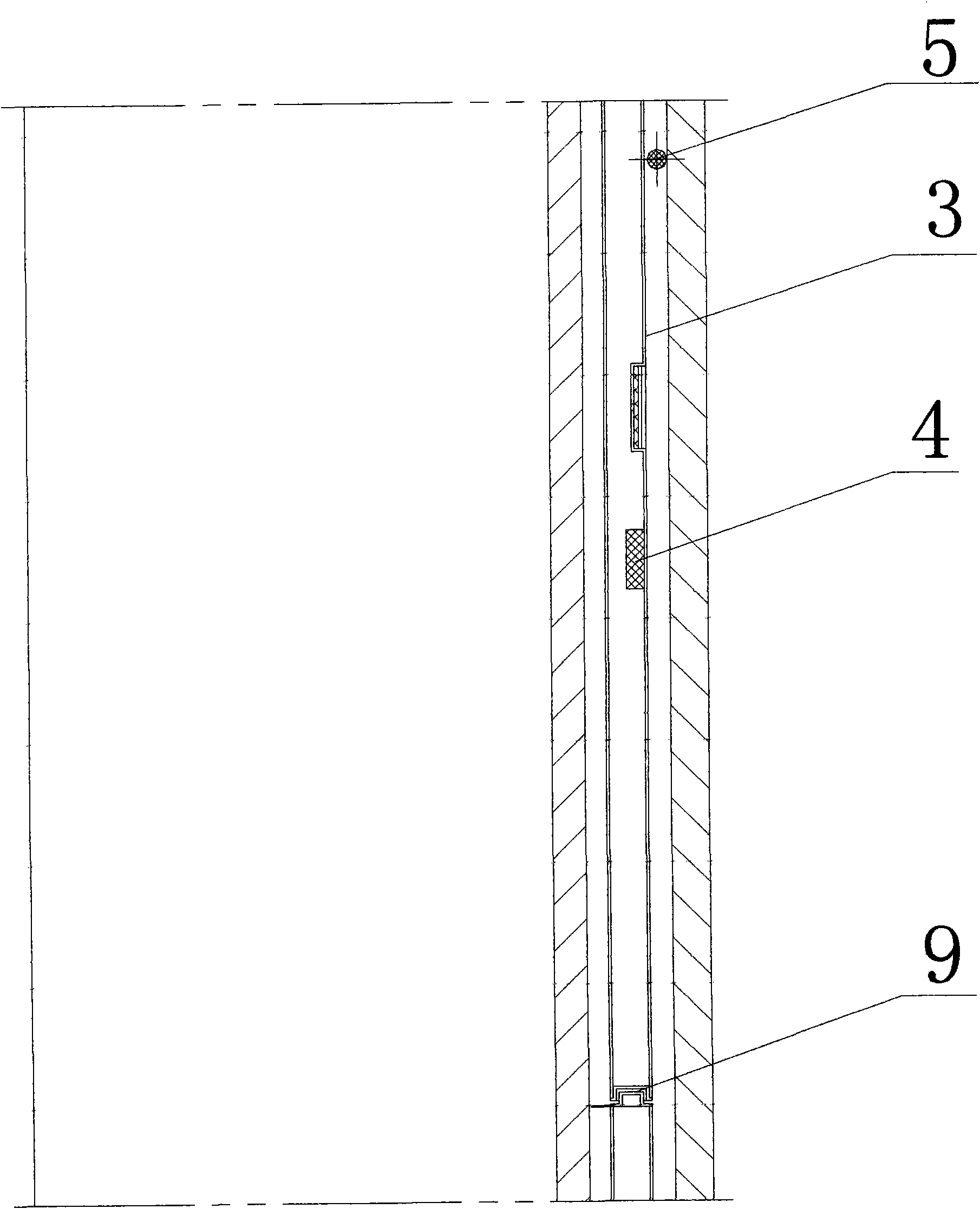
[0023] Embodiment 1: This embodiment includes an inner tube 1 and an outer tube 2, and a separate layer of stainless steel vacuum heat insulation tube 3 is arranged between the inner and outer tubes. The stainless steel vacuum heat insulation tube 3 is a stainless steel tube with a thickness greater than or equal to 0.3mm The double-layer stainless steel vacuum tube welded by the plate, the vacuum degree is higher than 1×10 -1 Pa. The stainless steel vacuum heat insulation pipe 3 is composed of a first stainless steel vacuum heat insulation pipe 31 and a second stainless steel vacuum heat insulation pipe 32 which are spliced ​​together in the axial direction. The first stainless steel vacuum heat insulation pipe 31 is insulated from the second stainless steel vacuum heat insulation pipe. A groove 4 with a concave-convex structure is provided between the butt ends of the pipes 32 , and the first stainless steel vacuum heat-insulated pipe 31 and the second stainless steel vacuum...

Embodiment 2

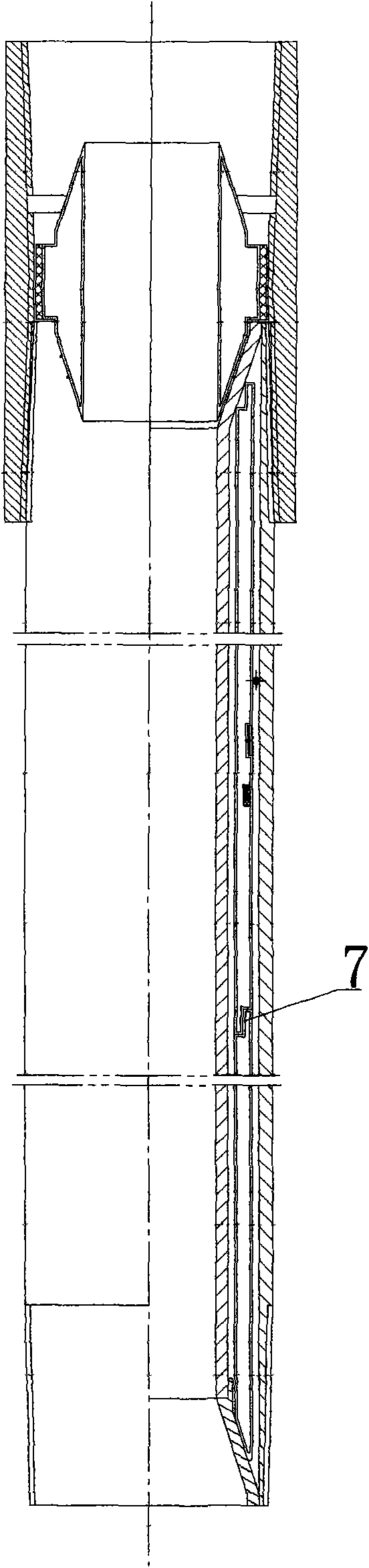
[0024] Embodiment 2: This embodiment is basically the same as Embodiment 1, except that the butt end faces of the first stainless steel vacuum heat insulation pipe 31 and the second stainless steel vacuum heat insulation pipe 32 are steps 7 .

Embodiment 3

[0025] Embodiment 3: This embodiment is basically the same as Embodiment 1, except that the butt end faces of the first stainless steel vacuum heat insulation pipe 31 and the second stainless steel vacuum heat insulation pipe 32 are plane 8 .


PUM

PropertyMeasurementUnit
Wall thicknessaaaaaaaaaa
Lengthaaaaaaaaaa

Abstract

The invention relates to a vacuum compound heat insulating pipe which comprises an inner pipe and an outer pipe and is characterized in that at least one layer of independent stainless steel or carbonsteel vacuum heat insulating pipe is arranged between the inner pipe and the outer pipe, and the vacuum heat insulating pipe is a double-layer vacuum pumping pipe only formed by welding a stainless steel plate or a carbon steel plate. The vacuum compound heat insulating pipe has the heat insulating life of more than eight years, and the heat insulating effect can be ensured. In addition, when theinner pipe and the outer pipe of the vacuum compound heat insulating pipe are damaged, the stainless steel vacuum heat insulating pipe is conveniently replaced, can be repeatedly used and reduces themaintenance cost in a subsequent maintenance process.

Description

technical field [0001] The invention relates to heat insulation pipes, in particular to a vacuum composite heat insulation pipe, which is suitable for heat preservation and transportation of liquids and gases, and is especially suitable for downhole oil pipes for heavy oil steam injection and oil production. The vacuum composite heat insulation pipe can reduce steam injection Loss, improve heat utilization. Background technique [0002] The oil pipes currently used are generally installed in the underground of a kilometer. Due to the depth of the well, the thick oil, the large temperature difference of heat transfer in the downhole, and the high thermal conductivity of the steel pipe, the heat loss is very large when steam is injected into the oil pipe. Therefore, this oil pipe must be used. Insulated tubing with superior thermal performance. Existing heat insulation oil pipe insulation systems are usually based on glass wool, aluminum silicate wool and other heat insulatio...

Claims


Application Information

Patent Timeline
IPC IPC(8): F16L59/065E21B17/00E21B43/24
Inventor 白明军吴平张琰周生宣
Owner 湖北贵族真空科技股份有限公司
Why Eureka
Try Eureka