Method for detecting fault of rotating diode

A rotating diode and fault detection technology, which is applied in the direction of measuring electricity, measuring devices, measuring electrical variables, etc., can solve the problems of inability to distinguish magnetic flux changes, inaccurate measurements, high misoperation rate or refusal rate, and achieve Guarantee the effect of normal and safe operation

Inactive Publication Date: 2010-02-10
NR ELECTRIC CO LTD +1
View PDF0 Cites 22 Cited by
  • Summary
  • Abstract
  • Description
  • Claims
  • Application Information

AI Technical Summary

Problems solved by technology

The sudden change method usually detects the influence of the sudden change of the current of the faulty rotating diode on the magnetic flux of the motor core, detects the sudden change of the magnetic flux of the iron core, and then judges the fault of the rotating diode. This method has a small scope of application. For multi-phase rectification Due to the large number of phases of the rotating diode, when a certain phase fails, it has little influence on the magnetic flux of the motor iron core, and it is usually impossible to distinguish the magnetic flux change caused by the fault condition from the magnetic flux change caused by the normal adjustment of the excitation current, so that it cannot Correctly judge the fault of the rotating diode; the pulse counting method adopts installing an inductor on the motor base, and when the rotating diode branch has current flowing through the inductor and rotates through the inductor, a pulse waveform is induced in the inductor, and the pulses of the inductor are counted. Therefore, it can be judged that there is no current flowing after the fault of the rotating diode, because the stability of the sensor is poor, including the sensor being displaced by collision, resulting in inaccurate measurement, or the sensor (Hall device, etc.) itself is polluted by oil and dust to cause signal Distortion, etc., so the method has a high false action rate or rejection rate

Method used


Image

  • Method for detecting fault of rotating diode
  • Method for detecting fault of rotating diode
  • Method for detecting fault of rotating diode

Examples


Embodiment Construction

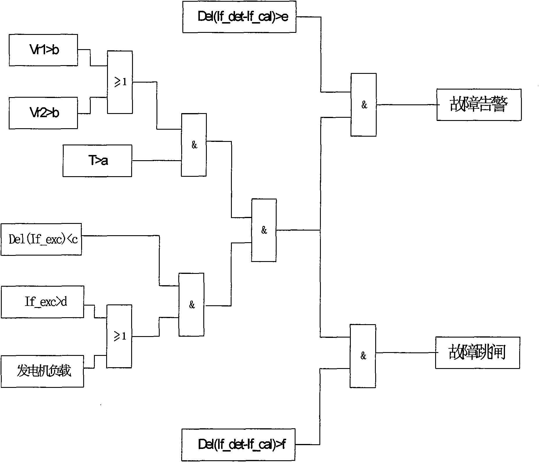
[0033] The specific implementation method of the present invention is as shown in Figure 1: among the figure V r1 For harmonic rms characteristic measurements 1, V r2 Harmonic RMS characteristic measurement 2, If_exc is the current measurement value of the excitation device, If_det is the actual value of the field winding current of the exciter, If_cal is the calculated value of the field winding current of the exciter, T is the delay time, a, b, c, d , e, f are the tuning parameters, which are set according to the excitation system parameters.

[0034] 1. The harmonic current in the excitation winding is detected by two sensors with different principles: DC shunt measurement method and Luo coil measurement method. Collect two exciter excitation winding currents, analyze and calculate them through FFT (FastFourierTransform, Fast Fourier Transform) respectively, and obtain the characteristic measurement of harmonic RMS 1 (V r1 ) (measurement of the excitation winding current ...


PUM


Abstract

The invention discloses a method for detecting the fault of rotating diodes, which is characterized in that whether the rotating diode is at fault or not is judged by detecting specific value of the effective values of a first, a second, a third, a fourth, a fifth and a sixth subharmonic and the effective value of a twenty second subharmonic of exciting winding current of an exciter; when the specific value of the sum of the effective values of the first, the second, the third, the fourth, the fifth and the sixth subharmonic and the effective value of the twenty second subharmonic is less than0.1, the rotating diode is in normal operation, and when the specific value is more than 0.1, the rotating diode is at fault; when the specific value of the sum of the effective value of the first, the third and the fifth subharmonic and the effective value of the twenty second subharmonic is more than 50, the rotating diode has arm short fault, and when the specific value is less than 10 and more than 1, the rotating diode is in one phase open circuit, when the specific value is more than 10, the rotating diode is in multi-phase open circuit. The fault judging method of rotating diode of theinvention provides accurate and suitable control strategy for a generator when the rotating diode is at fault, and ensures that excitation system and the generator is in normal and safe operation.

Description

technical field [0001] The invention relates to a method for detecting and judging a rotating diode fault and a device using the method. Background technique [0002] The correct judgment of the fault of the rotating diode in the brushless excitation generator is very important for the safe operation of the generator and the rotating diode. At present, there are two main conventional methods for judging the fault of rotating diodes: [1,2] and pulse counting method [3,4] . The sudden change method usually detects the influence of the sudden change of the current of the faulty rotating diode on the magnetic flux of the motor core, detects the sudden change of the magnetic flux of the iron core, and then judges the fault of the rotating diode. This method has a small scope of application. For multi-phase rectification Due to the large number of phases of the rotating diode, when a certain phase fails, it has little influence on the magnetic flux of the motor iron core, and i...

Claims


Application Information

Patent Timeline
Patent Type & Authority Applications(China)
IPC IPC(8): G01R31/26G01R31/02
Inventor 刘为群吴龙
Owner NR ELECTRIC CO LTD
Why Eureka
Try Eureka