Passive millimeter wave imaging system

A millimeter-wave imaging, passive technology, applied in radio wave measurement system, radio wave reflection/re-radiation, utilization of re-radiation, etc., can solve the problems of low image resolution, long imaging time, poor real-time performance, etc., and achieve image resolution High efficiency, short imaging time, and reduced system cost

Active Publication Date: 2011-09-07
HARBIN INST OF TECH
View PDF0 Cites 2 Cited by
  • Summary
  • Abstract
  • Description
  • Claims
  • Application Information

AI Technical Summary

Problems solved by technology

[0003] The present invention aims to solve the problems of long imaging time, poor real-time performance, low resolution of obtained images, and high cost caused by the need to use a large number of receivers in the existing millimeter wave imaging system, thereby providing a passive millimeter wave imaging system

Method used


Image

  • Passive millimeter wave imaging system
  • Passive millimeter wave imaging system
  • Passive millimeter wave imaging system

Examples


specific Embodiment approach 1

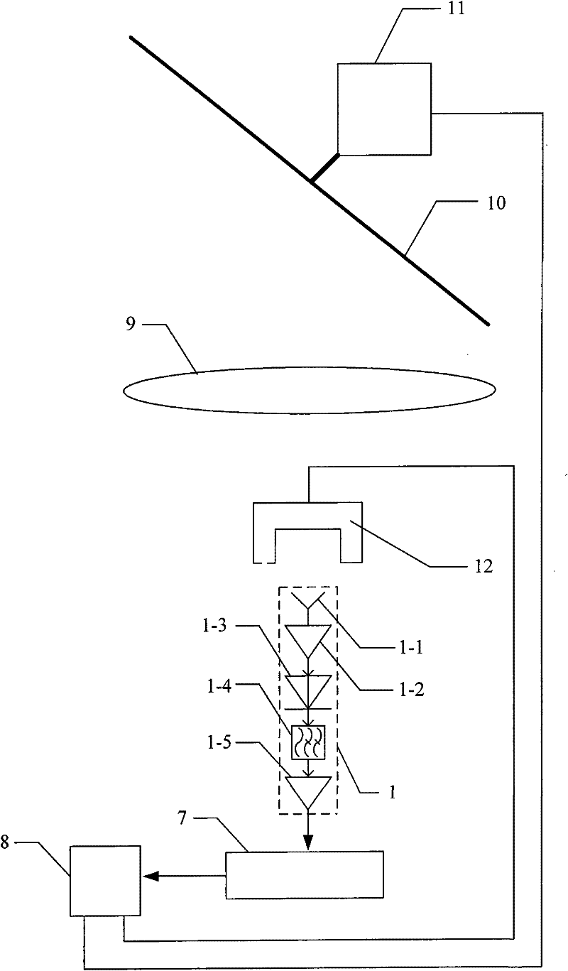
[0007] Specific implementation mode 1. Combination figure 1 Illustrate this specific embodiment, passive millimeter-wave imaging system, it comprises dielectric lens 9 and metal reflection plate 10, passive millimeter-wave imaging system also comprises radiometer system 1, digital acquisition circuit 7 and computer 8; Said radiometer system 1 is made up of A receiving antenna 1-1, a millimeter-wave band high-gain low-noise amplifier 1-2, a high-sensitivity square-law detector 1-3, a low-pass filter 1-4, and a low-frequency amplifier 1-5 are composed; the receiving antenna 1-1 The signal output end is connected to the signal input end of the millimeter-wave band high-gain low-noise amplifier 1-2, and the signal output end of the millimeter-wave band high-gain low-noise amplifier 1-2 is connected to the signal input end of the high-sensitivity square law detector 1-3 Connection, the signal output end of the high-sensitivity square law detector 1-3 is connected with the signal in...

specific Embodiment approach 2

[0012] Embodiment 2. The difference between this embodiment and the passive millimeter-wave imaging system described in Embodiment 1 is that it also includes a stepping motor 11 with a controller, and the stepping motor 11 with a controller The shaft of the rotor is fixedly connected with the center of the metal reflector 10; the stepper motor control signal output end of the computer 8 is connected with the control signal input end of the stepper motor 11 with the controller. The stepping motor 11 with a controller is used to drive the metal reflector 10 to rotate.

[0013] The metal reflector in this embodiment can change the propagation direction of the electromagnetic wave by using the reflection effect of the metal on the electromagnetic wave, and use the stepper motor 11 to drive the metal reflector 10 to rotate around the axis to complete the longitudinal scanning of the target to be measured. The side of the metal reflector 10 facing the lens should have relatively hig...

specific Embodiment approach 3

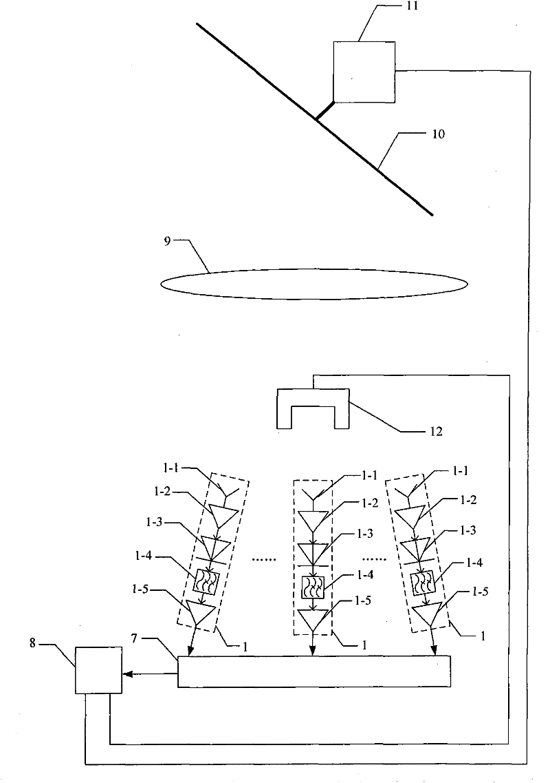
[0014] Specific implementation mode three, combination figure 2 This specific embodiment is described. The difference between this specific embodiment and the passive millimeter-wave imaging system described in the first or second specific embodiment is that the radiometer system 1 is a multi-group radiation array arranged according to the spatial Nyquist sampling law. meter system 1, and the receiving antenna 1-1 of each radiometer system 1 points to the center of the dielectric lens 9, and the phase center of the receiving antenna 1-1 of each radiometer system 1 is to the center of the illumination surface of the dielectric lens 9 The points are all at the same distance.


PUM


Abstract

The invention discloses a passive millimeter wave imaging system and relates to a millimeter wave imaging system. The passive millimeter wave imaging system solves the problems of long imaging time of the system, poor real-time property and low resolution of an obtained image caused by the way of focal plane array imaging of the existing millimeter wave imaging system. A metal reflection plate ofthe passive millimeter wave imaging system reflects electromagnetic waves radiated by a target to be tested onto a receiving antenna by aggregation via a medium lens, the received signals are processed by a millimeter wave band high-gain low-noise amplifier, a high-sensitivity square law detector, a low-pass filter and a low-frequency amplifier in sequence and then collected by a digital collection circuit, and the collected signals are transmitted into a computer for carrying out imaging processing. The passive millimeter wave imaging system is applicable to the field of security.

Description

technical field [0001] The invention relates to a millimeter wave imaging system. Background technique [0002] Any object above absolute zero will radiate electromagnetic waves with different bands, and the energy radiated by objects of different materials is the product of emissivity and absolute temperature. Electromagnetic waves in the millimeter wave band have good diffraction characteristics and can penetrate clothing to detect objects carried by the human body. The existing millimeter-wave imaging system uses radiometers to form the focal plane to obtain images. The focal plane components mainly use direct detection radiometers and superheterodyne radiometers. The former is easier to form a focal plane array, but it is more difficult for the detector Sensitivity requirements are high, and it is not easy to obtain high-resolution images; the latter has high temperature resolution, but the circuit structure is complex and bulky, and there are more problems with antenna...

Claims


Application Information

Patent Timeline
Patent Type & Authority Patents(China)
IPC IPC(8): G01S13/89G01S7/40
Inventor 邱景辉陈立甲王楠楠庄重李高飞
Owner HARBIN INST OF TECH
Why Eureka
Try Eureka