Real-time frequency domain super-resolution direction estimation method and device

A azimuth estimation and super-resolution technology, which can be used in measurement devices, re-radiation of sound waves, and use of re-radiation. It can solve problems such as poor robustness, slow calculation speed, and difficulty in handling broadband target signal resolution

Inactive Publication Date: 2010-02-10
INST OF ACOUSTICS CHINESE ACAD OF SCI
View PDF0 Cites 26 Cited by
  • Summary
  • Abstract
  • Description
  • Claims
  • Application Information

AI Technical Summary

Problems solved by technology

[0008] The purpose of the present invention is to overcome the deficiencies of the prior art, solve the problems of slow calculation speed, poor robustness, difficulty in processing broadband target signals and low resolution in the prior art, and provide a fast and robust high-resolution Accurate orientation estimation method and device

Method used


Image

  • Real-time frequency domain super-resolution direction estimation method and device
  • Real-time frequency domain super-resolution direction estimation method and device
  • Real-time frequency domain super-resolution direction estimation method and device

Examples


Embodiment 1

[0076] Such as Figure 5 As shown, the specific steps of the real-time high-resolution orientation estimation method and device for linear arrays in this embodiment are as follows:

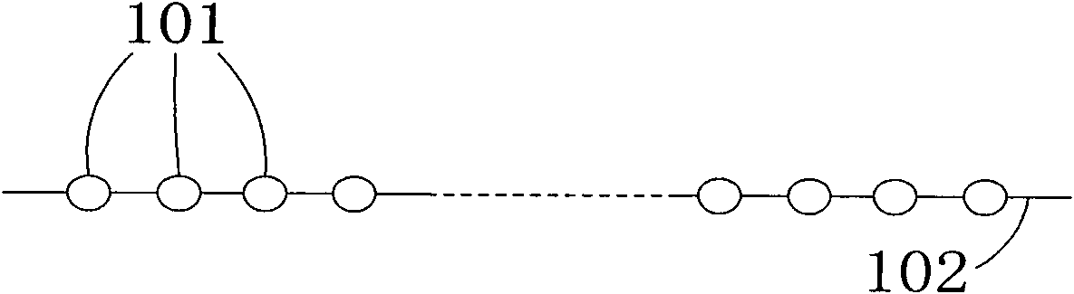
[0077] Step 501: Use a single line array to receive a spatio-temporal two-dimensional signal, so as to obtain time-domain data of each element of the line array.

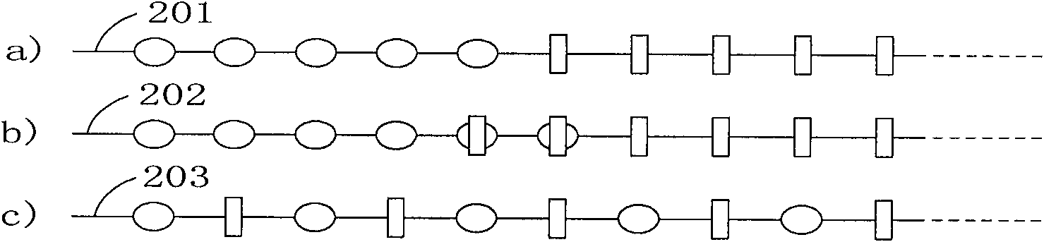
[0078] Step 502: logically divide the line array to obtain M 1 a sub-array;

[0079] In this step, there are mainly three ways to divide the sub-arrays, such as figure 2 As shown, 201 is a non-overlapping sub-array division method, which has a small amount of calculation and is suitable for a line array that is not very long; when the distance between the centers of each sub-array is too large, the non-overlapping sub-array division The method will cause grating lobes to appear in the output beam; 202 is the sub-array overlapping division method, which can avoid the occurrence of grating lobes due to the overlapping of array element...


PUM


Abstract

The invention provides a real-time frequency domain super-resolution direction estimation method and a device, and the method comprises the following steps: 1) dividing a linear array for obtaining M1sub-arrays; 2) respectively carrying out beamforming on a time-space two-dimensional signal of each sub-array for obtaining an output beam of each sub-array on the scanning direction; 3) carrying outsynthesis treatment on the output beams of various sub-arrays on the scanning direction for obtaining a multi-sub-array synthetic beam; and 4) and obtaining the target direction according to the multi-sub-array synthetic beam obtained by the step 3). The invention provides the real-time frequency domain super-resolution direction estimation device. The method and the device have the following technical effects: (1) the calculation is highly efficient, the speed is fast, the DSP engineering is convenient to realize, and the real-time treatment can be realized; (2) the method and the device areapplicable to broadband noise target direction finding; (3) the high-resolution beam can be obtained; and (4) compared with the frequency domain beamforming algorithm in the prior art, the method andthe device can obtain beam output with even narrow main lobe and even weak strength of a side lobe, thereby obtaining the target direction estimation with higher resolution.

Description

technical field [0001] The invention belongs to the field of sonar digital signal processing, in particular to a real-time frequency domain super-resolution orientation estimation method and device. Background technique [0002] A basic problem of sonar digital signal processing is azimuth estimation, which is to determine the direction of the space signal of interest, also known as target direction finding. High-resolution azimuth estimation refers to the use of a certain algorithm to process the two-dimensional space-time signal radiated or reflected by the target array to obtain a high-resolution estimate of the target azimuth. Super-resolution azimuth estimation technology can surpass the performance of traditional high-resolution technology, and has a wide range of applications in the fields of sonar, radar and communication. [0003] At present, typical high-resolution orientation estimation algorithms for sonar include: Capon method, narrow-band two-dimensional frequ...

Claims


Application Information

Patent Timeline
Patent Type & Authority Applications(China)
IPC IPC(8): G01S15/06
Inventor 田彪李宇黄海宁
Owner INST OF ACOUSTICS CHINESE ACAD OF SCI
Why Eureka
Try Eureka