
Dutyfactor adjusting method and circuit

A technology for adjusting circuits and adjusting methods, applied in electrical components, generating electric pulses, automatic control of power, etc., can solve the problems of easy interference of signals, narrow duty cycle adjustment range, and comparators affecting judgment accuracy, etc., and achieve stability. The effect of good performance, wide adjustment range and high output precision

Inactive Publication Date: 2010-02-10
IPGOAL MICROELECTRONICS (SICHUAN) CO LTD
View PDF0 Cites 17 Cited by
  • Summary
  • Abstract
  • Description
  • Claims
  • Application Information

AI Technical Summary

Problems solved by technology

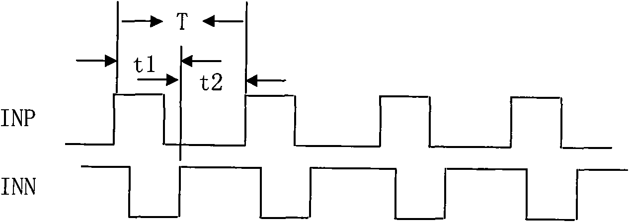
Its adjustment range is limited by the inversion (rise or fall) time. Too long inversion time will make the signal susceptible to interference, and the limited inversion time makes the adjustment range of the duty cycle narrow
[0003] For the detection of the duty cycle, the traditional method is to use the DC level of the input differential signal for comparison, and the DC offset of the comparator will seriously affect its decision accuracy

Method used


Image

  • Dutyfactor adjusting method and circuit
  • Dutyfactor adjusting method and circuit
  • Dutyfactor adjusting method and circuit

Examples


Embodiment 2

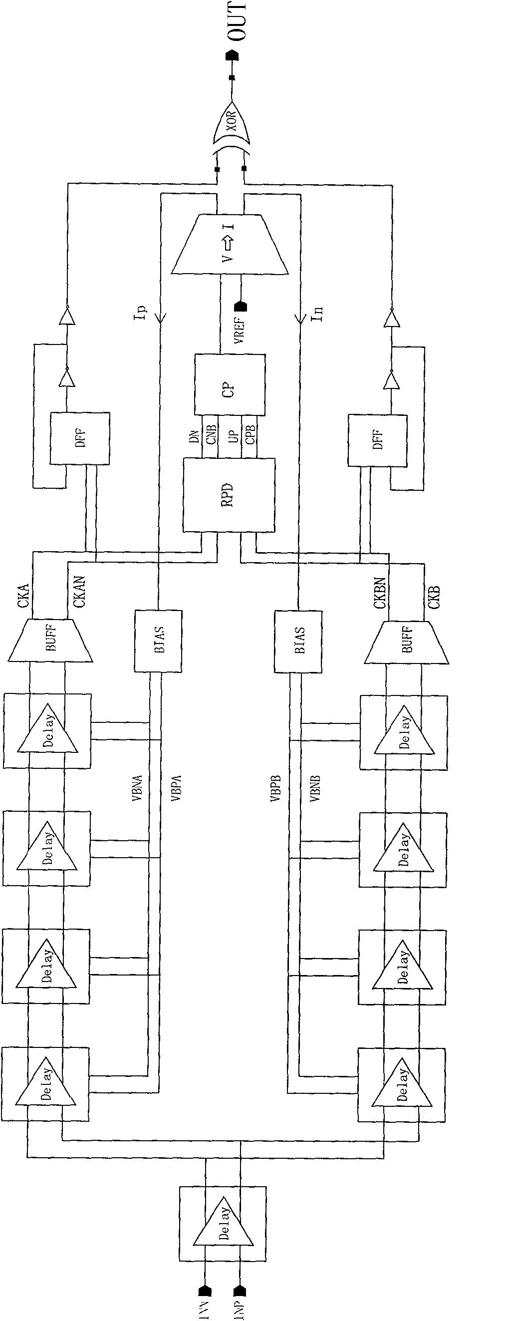
[0037] use as image 3 In the structure shown, the synthesized output unit adopts two two-frequency dividers and a symmetrical XOR unit, and other units are the same as the previous ones.

[0038] The charge pumps are configured with equal weights.

[0039] The final output OUT terminal is an output waveform with a duty ratio of 49.5%.

[0040] When the duty ratio is 1:1, the clock signal can be divided by N, such as image 3 The structure shown is that after frequency division by 4, the differential signal is directly input to the two input terminals of the charge pump; because the frequency division circuit, especially the high frequency division ratio circuit, can obtain an input signal with a duty ratio strictly 1:1; Initialize the charge pump voltage first, then input the frequency-divided signal to the charge pump circuit, after an even number of cycles 2*M (take M=100), stop the input signal, then its output level should remain unchanged; if A rise indicates that the...


PUM


Abstract

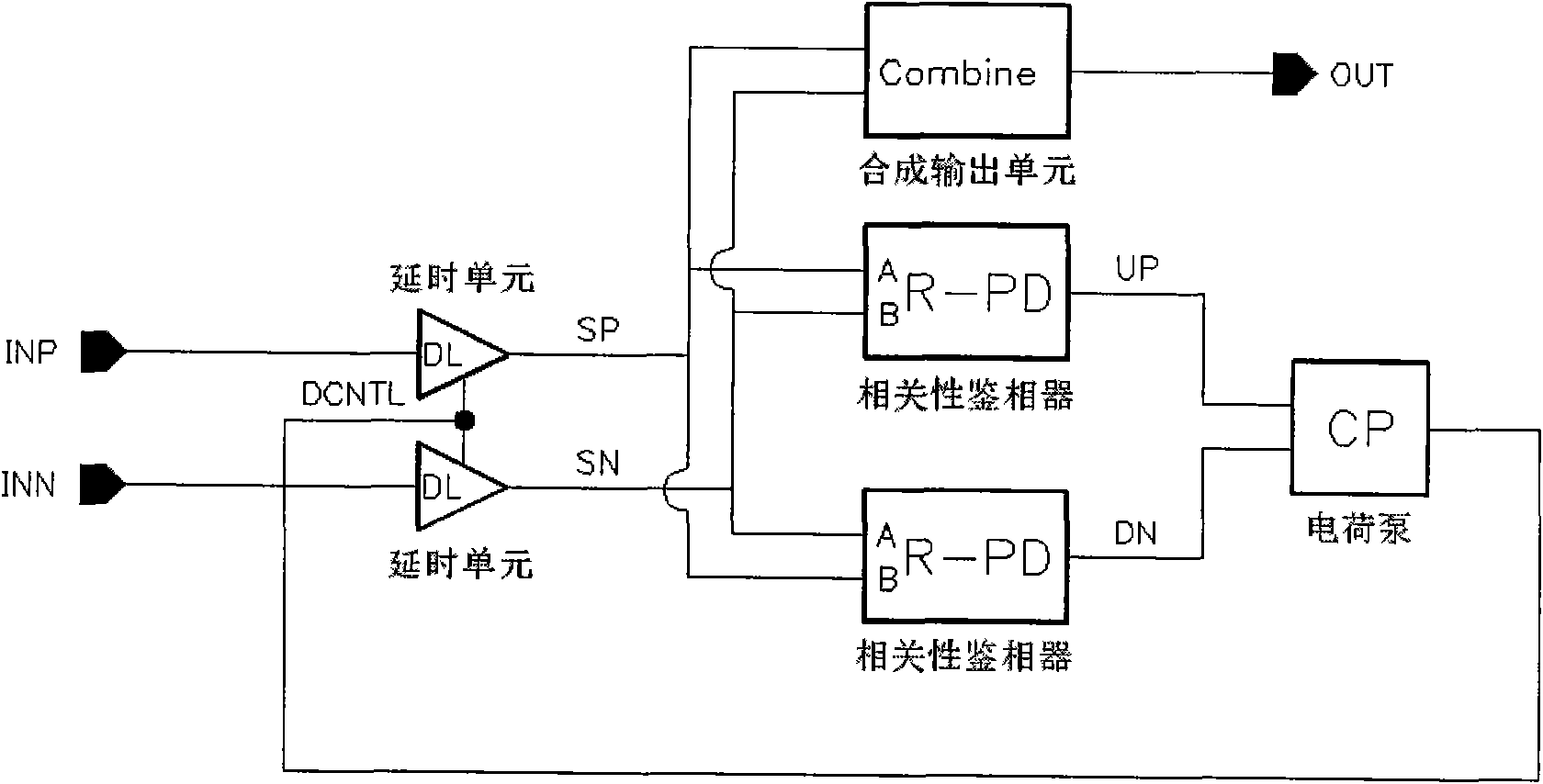
The invention discloses a dutyfactor adjusting method and a circuit. In the invention, two symmetrical delay units with opposite control logic input differential signals INP and INN carry out relativedelay detection on the differential signals, then the delay units are connected with correlation phase detectors, then the correlation phase detectors are connected with a charge pump, the output ofthe charge pump forms a loop with the two relay units, and the dutyfactor is adjusted at last, thereby a signal with the output dutyfactor of an output unit of 1:1 is synthesized. The invention can widen the adjusting scope of the duryfactor, and can theoretically realize the output of random preset dutyfactor; the structure of an implementation circuit is completely symmetrical, and high output precision (namely dutyfactor output signal with high precision) can be realized through favorable matching and process compensation; and an equivalent model of the circuit is a first order pole circuit, and the stability is good.

Description

technical field [0001] The invention relates to a duty ratio circuit, in particular to a duty ratio adjustment method and circuit which utilizes a correlation phase detector to detect a duty ratio error, utilizes a charge pump to accumulate errors, and utilizes a controllable delay unit to adjust the duty ratio. Background technique [0002] Duty cycle adjustment is particularly important for half-rate transmission clocks. The traditional duty cycle adjustment circuit is generally realized by adjusting the flipping threshold of signal transmission. By increasing or reducing the flipping threshold, the pulse width of high and low levels is changed, so as to realize Adjustment of duty cycle. Its adjustment range is limited by the inversion (rising or falling) time. Too long inversion time will make the signal susceptible to interference, and the limited inversion time makes the adjustment range of the duty cycle narrow. [0003] For the detection of the duty cycle, the tradit...

Claims


Application Information

Patent Timeline
IPC IPC(8): H03K3/017H03K5/156H03L7/00
CPCH03K5/1565
Inventor 武国胜全勇
Owner IPGOAL MICROELECTRONICS (SICHUAN) CO LTD
Learn More