LINC transmitter based on self-adapted peak clipping

A transmitter and peaking technology, which is applied to the shaping network of the transmitter/receiver, baseband system components, improved amplifiers to improve efficiency, etc., can solve the problem that the isolation synthesizer affects the overall efficiency of the LINC transmitter, etc., to improve Effects of average efficiency, maintenance of stability, and reduction of energy loss

Inactive Publication Date: 2010-02-10
UNIV OF ELECTRONIC SCI & TECH OF CHINA
View PDF0 Cites 14 Cited by
  • Summary
  • Abstract
  • Description
  • Claims
  • Application Information

AI Technical Summary

Problems solved by technology

The average efficiency of the isolated combiner will serio

Method used


Image

  • LINC transmitter based on self-adapted peak clipping
  • LINC transmitter based on self-adapted peak clipping
  • LINC transmitter based on self-adapted peak clipping

Examples


Embodiment Construction

[0024] Hereinafter, the present invention will be described in detail with reference to the accompanying drawings of embodiments of the present invention.

[0025] All terms employed in this disclosure are defined according to their functions in the present invention.

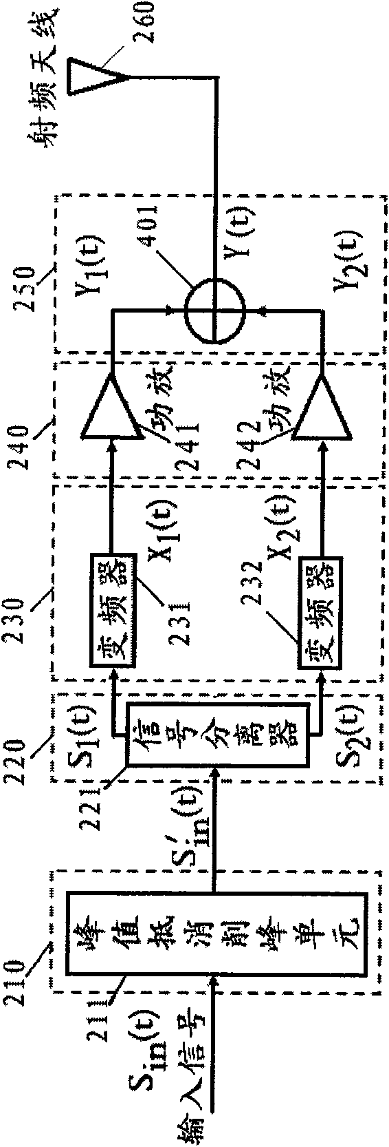
[0026] The invention relates to a LINC transmitter structure based on the idea of ​​optimizing the phase efficiency curve of the matching isolation synthesizer and the probability distribution curve of the additional phase modulation angle of the envelope signal. refer to figure 2 The structural block diagram of the LINC transmitter provided by the embodiment of the present invention. A LINC transmitter according to an embodiment of the present invention includes:

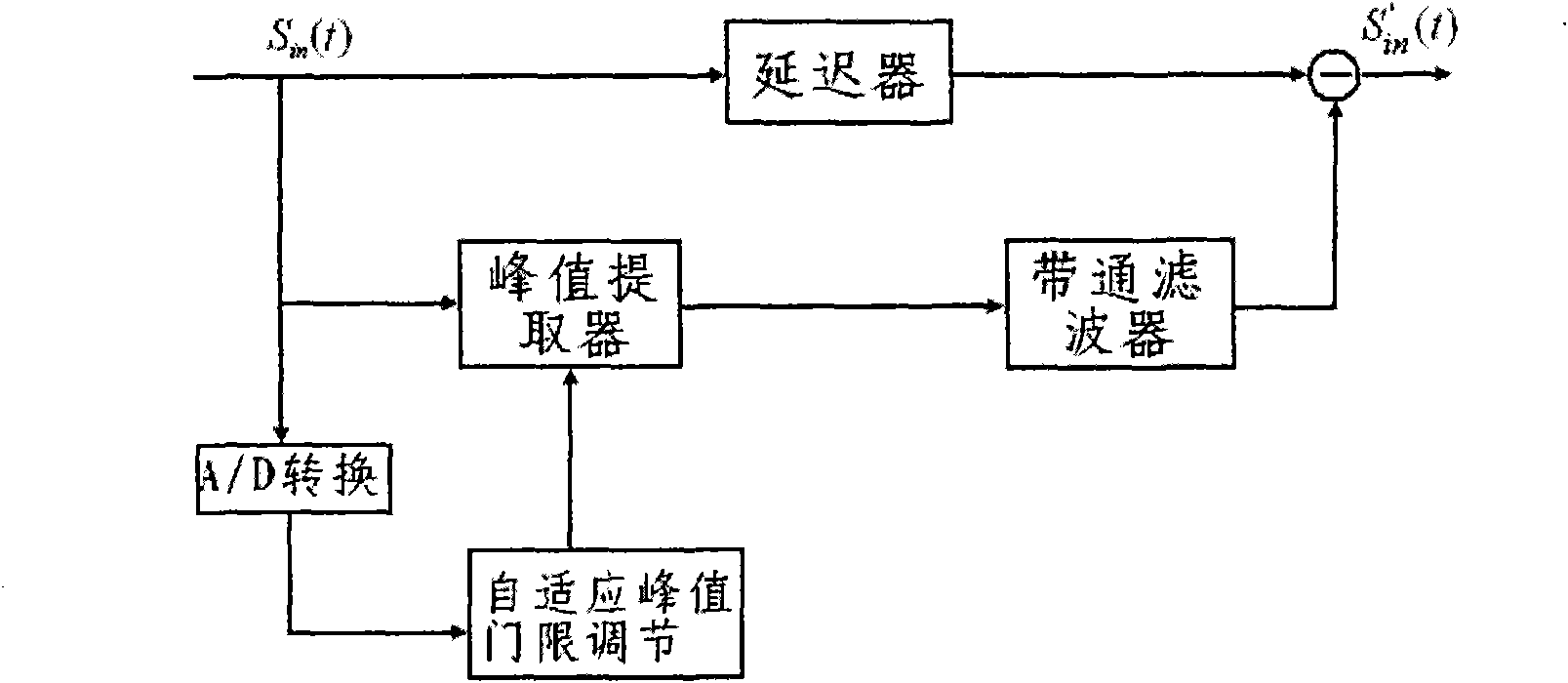
[0027] Peak cancellation peak clipping unit 210 . The input signal is processed by peak cancellation and peak clipping.

[0028] The input signal is S in (t)=r(t)e j[ωt+φ(t)] ;o≤r(t)≤R max ;

[0029] The signal after peak clipping is S in ...


PUM


Abstract

The invention provides an improved LINC transmitter device, comprising a peak counteracting and clipping unit, a signal separating unit, a frequency conversion unit, a signal amplifying unit and a signal synthesizing unit. The peak counteracting and clipping unit lowers the peak to average power ratio of input signals; the signal separating unit decomposes the signals after peak clipping into twoways of reversed phase signals with the same envelope card amplitude; the frequency conversion unit respectively converts the two ways of signals which are output by the signal separating unit to radio frequency signals; the signal amplifying unit amplifies the power of the two paths of the radio frequency signals; and the signal synthesizing unit carries out power synthesis on the two paths of signals which are output by the signal amplifying unit to obtain output signals transmitted by a radiofrequency antenna. Through introduction of a window function peak clipping unit, an improved systemcan improve the total efficiency indexes of the system by enhancing the signal synthesis efficiency.

Description

technical field [0001] The invention relates to the technical field of wireless communication, in particular to a LINC transmitter structure applied in the field of wireless communication. Background technique [0002] With the establishment of 3G standards, a new generation of mobile communication technology has entered the stage of practical application. In order to meet the requirements of customers for high-speed data transmission with anyone at any time, any place, the modulation methods of the new generation of wireless communication systems are becoming more and more complex, and QPSK, 16QAM, 64QAM and other modulation methods with high spectrum utilization are generally used. . These signals have non-constant envelope characteristics, and the peak-to-average ratio characteristics put forward high requirements on the linearity of the power amplifier at the end of the transmitter. In addition, how to improve the efficiency of modern wireless communication systems is ...

Claims


Application Information

Patent Timeline
IPC IPC(8): H04L27/26H04L25/03H03F1/02
Inventor 何松柏杨玲尹世荣游飞
Owner UNIV OF ELECTRONIC SCI & TECH OF CHINA
Why Eureka
Try Eureka