Electric spark processing working solution circulating system with self-cleaning function

A circulation system and working fluid technology, applied in the direction of electric processing equipment, metal processing equipment, manufacturing tools, etc., can solve the problems of poor filtration accuracy, troublesome cleaning, frequent replacement of filter elements, etc., to achieve automatic cleaning, improve work efficiency, improve The effect of the filter effect

Active Publication Date: 2010-02-17
DIMON BEIJING CNC TECH
View PDF0 Cites 6 Cited by
  • Summary
  • Abstract
  • Description
  • Claims
  • Application Information

AI Technical Summary

Problems solved by technology

However, the surface of these filter elements will soon be covered with impurities produced during the process, causing blockage and making it impossible to continue to use. The only option is to replace the filter element, and there is often a large amount of dirt inside the filter, which is very troublesome to clean
As a result, the filter element is replaced frequently during use, the cleaning of the filter is time-consuming and laborious, and the use cost of the equipment is increased.
However, if a filter element with poor filtration accuracy is used in order to prolong the service life, it will not be able to meet the requirements of the processing area for the cleanliness of the processing fluid, and it will easily cause abnormal discharge during processing.

Method used


Image

  • Electric spark processing working solution circulating system with self-cleaning function

Examples


Embodiment Construction

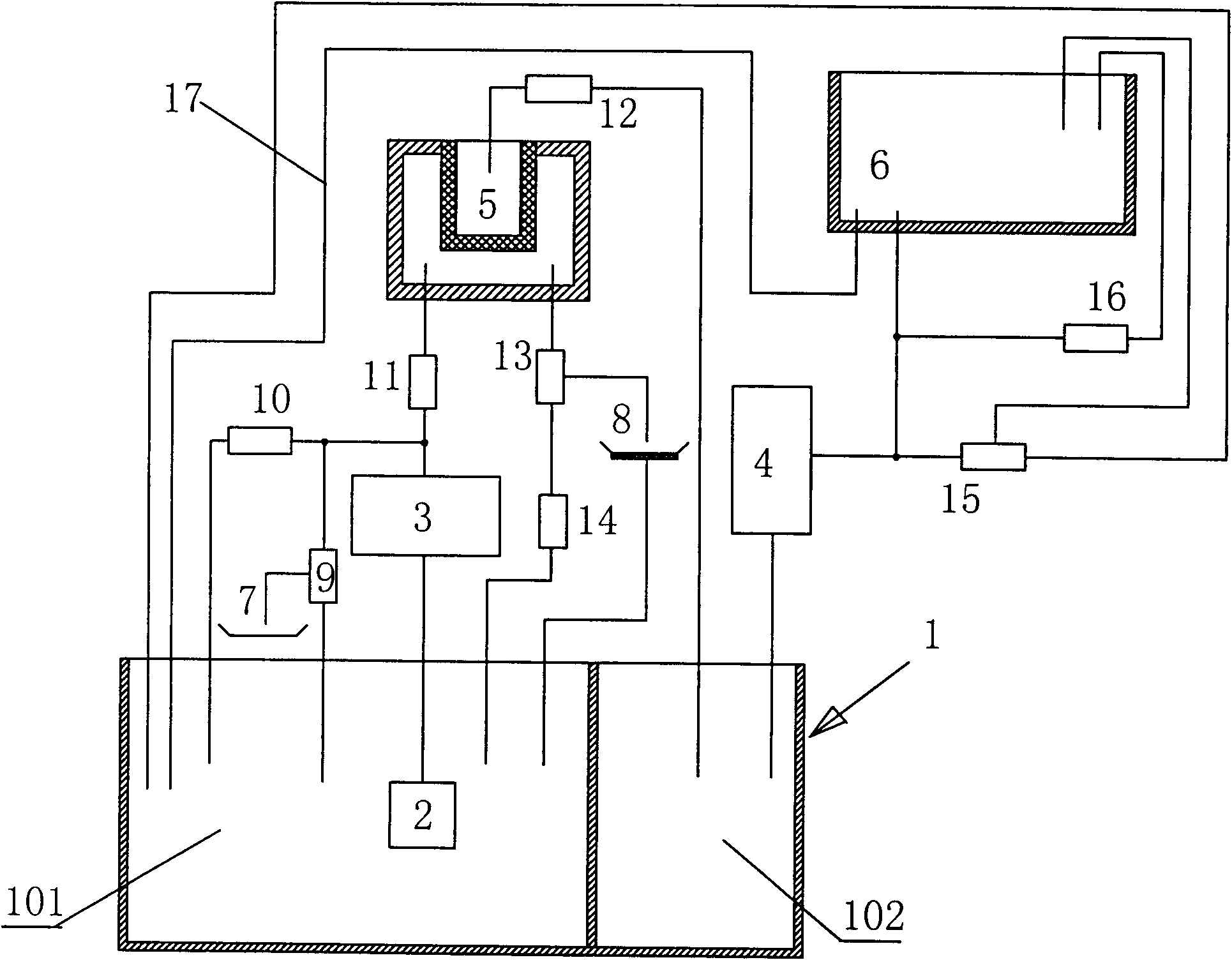
[0019] Such as figure 1 As shown, the EDM working fluid circulation system with self-cleaning function of the present invention is mainly composed of a liquid storage tank 1, a working fluid tank 6, a coarse filter 2, a cleaning filter 8, a filter pump 3, an upper liquid pump 4, a fine filter 5, various control valves 9-16 and pipelines; the position of the working fluid tank must be higher than that of the storage tank.

[0020] The EDM working fluid circulation system with self-cleaning function of the present invention divides the fluid storage tank into a dirty working fluid storage tank room for containing dirty working fluid and a clean working fluid storage tank room for clean working fluid. It can be installed independently, or as shown in the figure, a whole liquid storage tank can be separated into a dirty working fluid storage tank chamber 101 and a clean working fluid storage tank chamber 102 .

[0021] The EDM working fluid circulation system with self-cleaning f...


PUM


Abstract

The invention relates to an electric spark processing working solution circulating system with self-cleaning function, which comprises a solution storage box containing dirty working solution and clean working solution, a coarse filter and a working solution trough, wherein a solution outlet of a dirty working solution storage box chamber is communicated with an inlet of a fine filter through thecoarse filter, a filter pump and a control valve; an outlet of the fine filter goes into a clean working solution storage box chamber through a pipeline controlled by a valve; another solution outletof the box chamber is communicated with the working solution trough through a transmission pipeline with a solution feeding pump, a solution washing pressure valve pipeline and a solution pumping pressure valve pipeline are arranged on the transmission pipeline communicated with the working solution trough in parallel, and the working solution trough is communicated with the dirty working solutionstorage box chamber by another through pipeline; a clean circulation loop is arranged between the fine filter and the dirty working solution storage box chamber, a pipeline is communicated between the fine filter and the dirty working solution storage box chamber, an upper control valve and a lower control valve are arranged in the pipeline, the upper control valve is at least a three-way valve,a third control port of the upper control valve is communicated with a clean filter from top to bottom, and the clean filter is provided with a lower outlet communicated with the dirty working solution storage box chamber of the solution storage box.

Description

technical field [0001] The invention belongs to the technical field of special processing, and in particular relates to a self-cleaning electric discharge machining working fluid circulation system suitable for electric discharge forming processing. Background technique [0002] In EDM, the working fluid is used as the discharge medium, and the material is removed through the instantaneous high temperature generated by the spark discharge between the electrode and the workpiece to complete the process. During the machining process, the working fluid maintains a circulating state to provide support for EDM. The cleanliness of the working fluid is one of the key factors affecting the discharge state, so the working fluid circulation system has a direct impact on the effect of EDM, and is an important part of EDM equipment. [0003] The working fluid circulation system mainly plays two roles in the EDM system: one is to circulate clean working fluid to the processing area thro...

Claims


Application Information

Patent Timeline
IPC IPC(8): B23H11/00B23H1/00
Inventor 杨大勇付伟陈玉宁任连生崔志成
Owner DIMON BEIJING CNC TECH
Why Eureka
Try Eureka