
Overlapped shear wall with prefabricated part and cast-in-situ part and manufacturing method thereof

A technology of superimposed shear wall and manufacturing method, applied in the direction of walls, manufacturing tools, building components, etc., can solve the problems of high requirements on the comprehensive quality of construction personnel and construction management level, increase of structure self-weight, and increase of construction cost, etc. The effect of improving production efficiency and construction quality, saving materials and reducing construction difficulty

Inactive Publication Date: 2010-02-17
TONGJI UNIV
View PDF0 Cites 14 Cited by
  • Summary
  • Abstract
  • Description
  • Claims
  • Application Information

AI Technical Summary

Problems solved by technology

But practice has proved that this kind of pure external wall panel has the following disadvantages: 1) The prefabricated external wall panel is generally 70-90mm thick and equipped with a single-layer two-way steel mesh. The use of formwork wastes materials and increases the weight of the structure, which is unfavorable for earthquake resistance; 2) The inner side of the prefabricated wall panel is pre-embedded with horizontal and vertical reinforcement ribs, which makes it difficult to locate and bind the cast-in-place reinforcement, which indirectly increases the construction cost; 3 ) has higher requirements on the comprehensive quality of construction personnel and construction management level
It is estimated that the construction cost per building square meter of the shear wall structure house with external prefabricated wall panels will increase by about 700 yuan

Method used


Image

  • Overlapped shear wall with prefabricated part and cast-in-situ part and manufacturing method thereof
  • Overlapped shear wall with prefabricated part and cast-in-situ part and manufacturing method thereof

Examples


Embodiment Construction

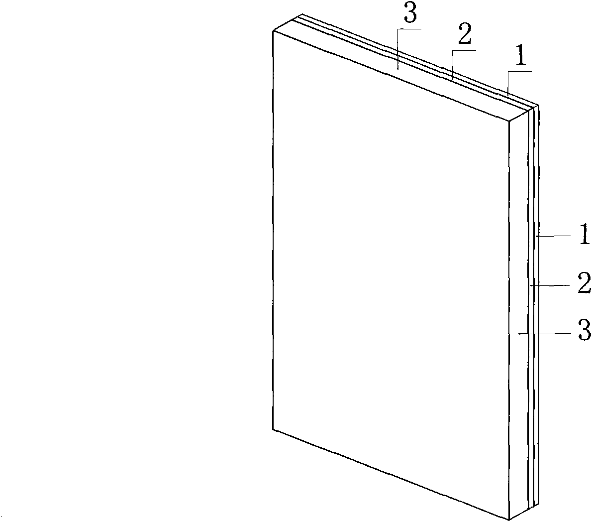
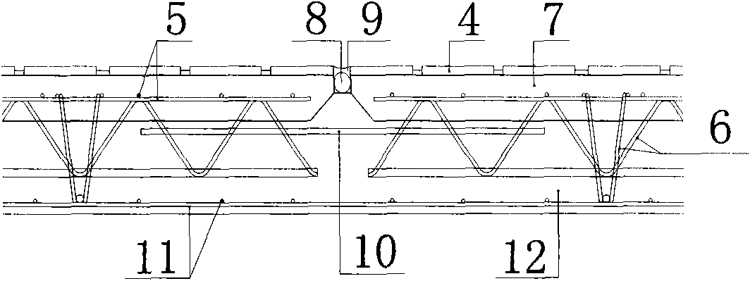
[0013] Such as figure 1 and figure 2 shown. The reinforced concrete shear wall is divided into two parts, one part is prefabricated in the factory (PCF slab), the other part is cast-in-place, and finally cast at the construction site to form a laminated shear wall.

[0014] The thickness of the prefabricated PCF board is generally controlled at 60-80mm. Generally, the width of a single PCF board is not greater than 3.0m, the height of the board is not greater than 6.0m, and the weight of the board is not greater than 2 tons.

[0015] When PCF boards are produced in the factory, a single-layer two-way steel mesh is arranged in the board according to the design calculation and structural requirements. The reinforcement grade is HRB335 or HRB400, and the diameter is not small. The exposed part of the laminated steel bar is anchored into the cast-in-place part to strengthen the interconnection between the prefabricated part and the cast-in-place part and improve the integrity ...


PUM


Abstract

The invention belongs to the technical field of the civil engineering building structure, in particular to an overlapped shear wall with a prefabricated part and a cast-in-situ part and a manufacturing method thereof. The traditional reinforced concrete shear wall is divided into two parts, wherein one part is prefabricated (a PCF plate) in a factory; the other part is cast in situ in a construction site; and after block cast, the prefabricated part (the PCF plate) and the cast-in-situ part are formed the overlapped shear wall. The plate thickness of the prefabricated PCF plate is commonly controlled at 60-80mm. The plate width of the single PCF plate is not greater than 3.0m, the plate height is not greater than 6.0m, and the plate weight is not greater than 2 tons. A single-layer two-wayreinforced bar net piece is configured in the plate; simultaneously, longitudinal and transverse overlapped reinforced bars are embedded at the inner side according to a distance of 450-600mm in advance, and the exposed parts of the overlapped reinforced bars are anchored into the cast-in-situ part. Compared with a pure external-hanging wall plate of a shear wall structure used at present, the invention lessens the self weight, lowers the construction difficulty, enhances the production efficiency and the construction quality and has energy saving and environmental protection.

Description

technical field [0001] The invention belongs to the technical field of building structures of civil engineering, and in particular relates to a novel energy-saving laminated shear wall partly prefabricated and partly cast-in-place and a manufacturing method thereof. Background technique [0002] The construction of reinforced concrete houses in my country is still dominated by the traditional on-site wet construction mode. This production method has serious waste of resources and energy, serious environmental pollution, high labor intensity, low productivity, chaotic management, and uneven product quality. , It is easy to produce inferior products and other characteristics. In order to change this status quo and cooperate with the construction of a resource-saving and environment-friendly society, the state has issued a series of relevant policies to encourage and promote the development of housing construction in the direction of industrialization. The key to the modernizat...

Claims


Application Information

Patent Timeline
IPC IPC(8): E04B2/86B28B1/00
Inventor 吕西林李检保王李果
Owner TONGJI UNIV
Learn More