Device and method for casting concrete continuous walls along gob-side entry retaining by mining working face

A technology for pouring concrete and retaining roadways, which is applied in mining equipment, shaft equipment, earthwork drilling and mining, etc. It can solve problems such as tight connection of roofs in difficult coal seams, difficulty in rigid formwork, and concrete that is prone to leakage of grout, and achieves good roofing effect, Not easy to leak slurry, good airtight effect

Active Publication Date: 2010-02-17
SHAANXI PIONEERING ARCHITECTURAL TECH
View PDF0 Cites 20 Cited by
  • Summary
  • Abstract
  • Description
  • Claims
  • Application Information

AI Technical Summary

Problems solved by technology

[0002] Traditional mining face gobside entry retention uses wooden piles, dense pillars, gangue bags, material stone walls or concrete diaphragm walls, while the concrete diaphragm walls use rigid formwork to set up the formwork. The construction disadvantages of these methods are that they require a lot of manpower and material resources , and the labor intensity is high, and the construction speed is slow; the rigid formwork is not easy to change with the change of the slope surface of the roof and floor, resulting in poor airtightness, easy grout leakage during the concrete pouring process, and the poured concrete is not dense, and it is difficult to be tightly combined with the coal seam roof

Method used


Image

  • Device and method for casting concrete continuous walls along gob-side entry retaining by mining working face
  • Device and method for casting concrete continuous walls along gob-side entry retaining by mining working face
  • Device and method for casting concrete continuous walls along gob-side entry retaining by mining working face

Examples


Embodiment Construction

[0022] Below in conjunction with accompanying drawing, content of the invention is further described:

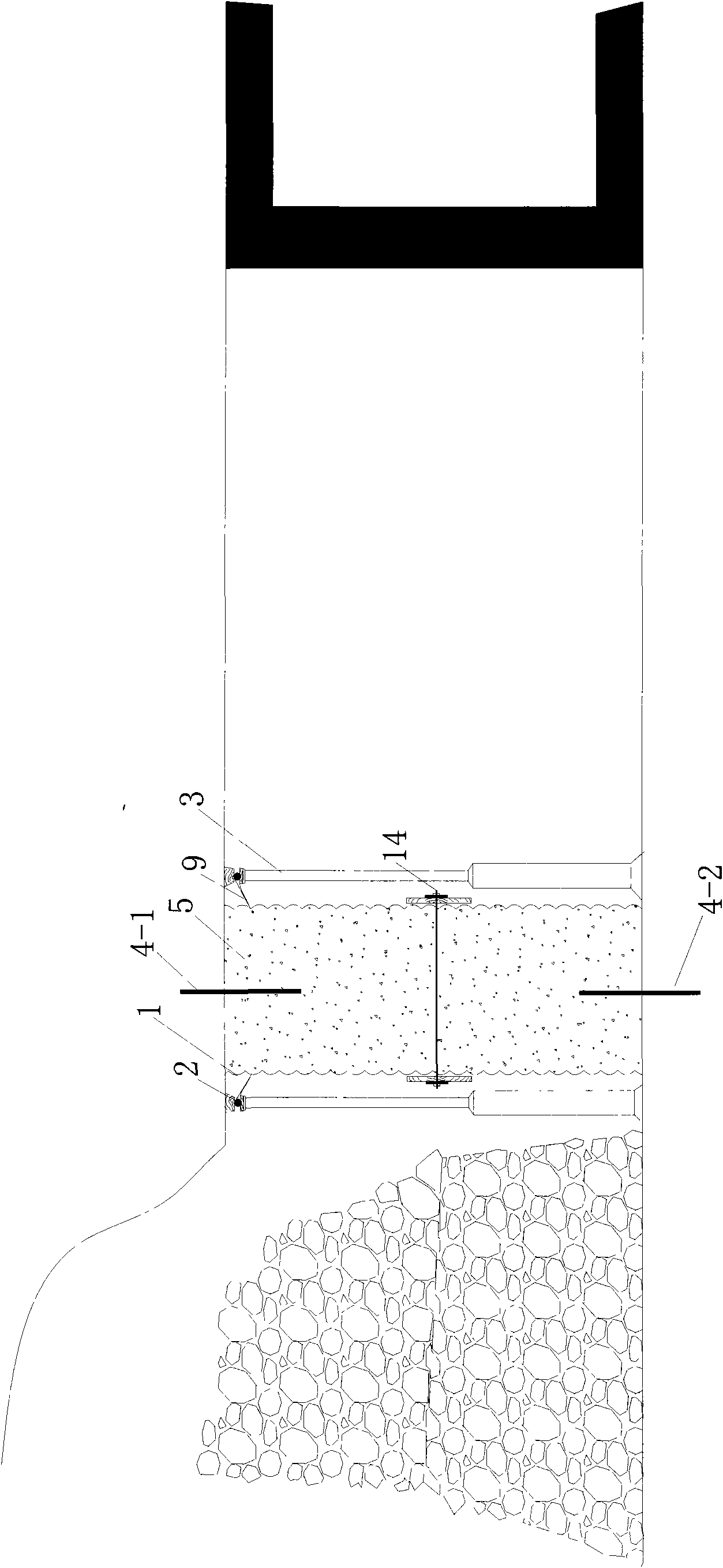
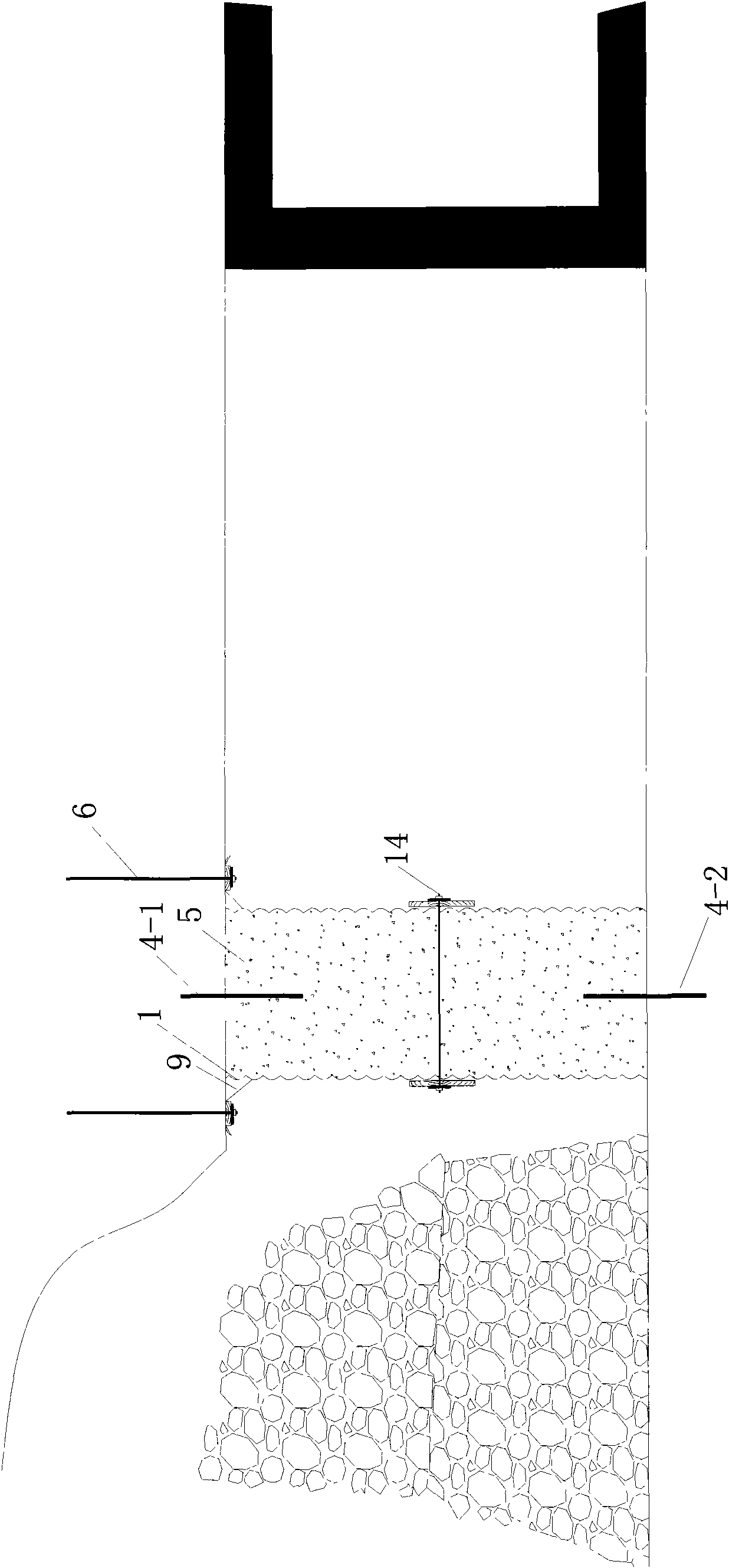
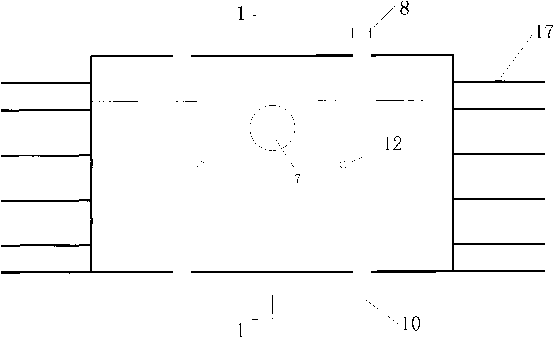
[0023] refer to Figure 1-Figure 4 As shown: a fiber flexible formwork 1 is composed of a main formwork 15 and a top formwork 16. The two sides of the fiber flexible formwork are respectively connected to the flange 9, and the flange 9 is equipped with a sleeve 11, and the sleeve 11 is penetrated with a The steel beam 2 and the flange 9 hang the fiber flexible formwork 1 on the coal seam roof through the single hydraulic prop 3 or the anchor rod 6, and the fiber flexible formwork 1 is respectively connected to the pouring port 7, the upper reinforcement opening 8, and the lower reinforcement reinforcement in turn. Port 10, limit hole 12, one end of the upper planting bar 4-1 is connected to the coal seam roof, the other end is inserted into the fiber flexible formwork 1 through the upper planting bar port 8 and fixedly connected with the concrete 5, and one end of the lower ...


PUM


Abstract

The invention discloses a device and a method for casting concrete continuous walls along gob-side entry retaining by a mining working face. A fiber flexible template is in cuboid shape or in cubicalshape, which is formed by a main body template and a top joint template and is connected with a flange, a casting opening, a reinforcing steel bar implanting opening, a spacing hole and a tiepiece. The method comprises the following steps: the fiber flexible template is manufactured in advance; the flexible template is hung over on a top plate of a coal seam through an individual hydraulic prop oran anchor rod by the flange; the exposure end of the implanted reinforcing steel bar is inserted in the flexible template through the reinforcing steel bar implanting opening; a leading screw penetrates into the spacing hole and two ends thereof are fixed by tray nuts; the casting opening is inserted with a concrete conveying pipe and is bonded; concrete is poured into the flexible template through the conveying pipe by a concrete pump; and finally the concrete continuous walls are formed. The invention has simple structure, high-speed construction, high work efficiency, good impermeability,uneasily slurry leaking property, densely filled concrete and good top joint effect, can carry out mechanized operation, adapts to the change of gradient of the roof and floor, and can be widely usedin the following industries, such as coal mine, metallurgical mine, water conservancy, underground construction and national defense and the like.

Description

technical field [0001] The invention relates to a concrete continuous wall, in particular to a device and a method for pouring a concrete continuous wall along a gob-side entry in a mining working face. Background technique [0002] Traditional mining face gobside entry retention uses wooden piles, dense pillars, gangue bags, material stone walls or concrete diaphragm walls, while the concrete diaphragm walls use rigid formwork to set up the formwork. The construction disadvantages of these methods are that they require a lot of manpower and material resources , and the labor intensity is high, and the construction speed is slow; the rigid formwork is not easy to change with the change of the slope surface of the roof and floor, resulting in poor airtightness, easy grout leakage during the concrete pouring process, and the poured concrete is not dense, and it is difficult to be tightly combined with the coal seam roof . Contents of the invention [0003] The purpose of th...

Claims


Application Information

Patent Timeline
Patent Type & Authority Applications(China)
IPC IPC(8): E21D11/10E21D11/12
Inventor 王晓利吴玉意
Owner SHAANXI PIONEERING ARCHITECTURAL TECH
Why Eureka
Try Eureka