Light-emitting diode illumination apparatus
A technology for light-emitting diodes and lighting devices, which is applied to lighting devices, fixed lighting devices, components of lighting devices, etc., can solve the problem of optimal operating temperature Problems such as operation under optimal conditions to achieve the effect of improving heat dissipation performance
- Summary
- Abstract
- Description
- Claims
- Application Information
AI Technical Summary
Problems solved by technology
Method used
Image
Examples
no. 1 example
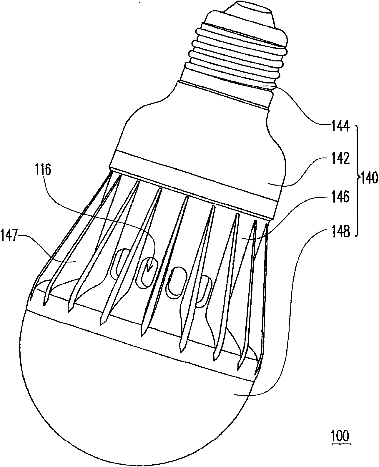
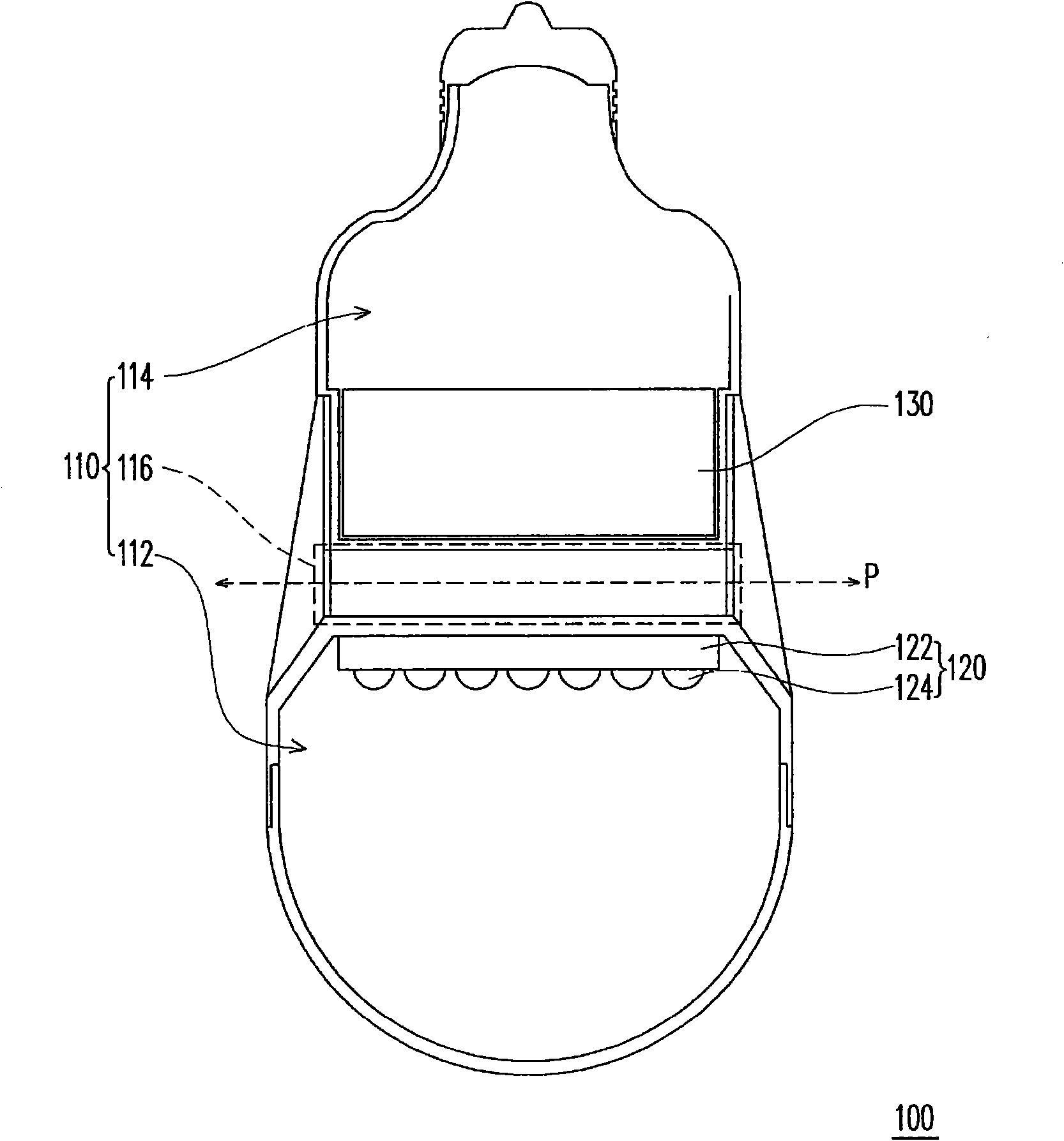
[0050] Figure 1A It is a three-dimensional schematic view of the LED lighting device according to the first embodiment of the present invention. Figure 1B for Figure 1A A cross-sectional schematic diagram of a light-emitting diode lighting device. Please also refer to Figure 1A and 1B , the LED lighting device 100 of this embodiment includes a casing 110 , an LED light source 120 and a power supply unit 130 . The casing 110 has a light source accommodation space 112 , a power supply accommodation space 114 and a thermal barrier passage 116 communicating with the outside world, wherein the first thermal isolation passage 116 is located between the light source accommodation space 112 and the power supply accommodation space 114 . The LED light source 120 and the power supply unit 130 are disposed in the light source accommodating space 112 and the power supply accommodating space 114 respectively.
[0051] The types of the housing 110, the LED light source 120 and the pow...
no. 2 example
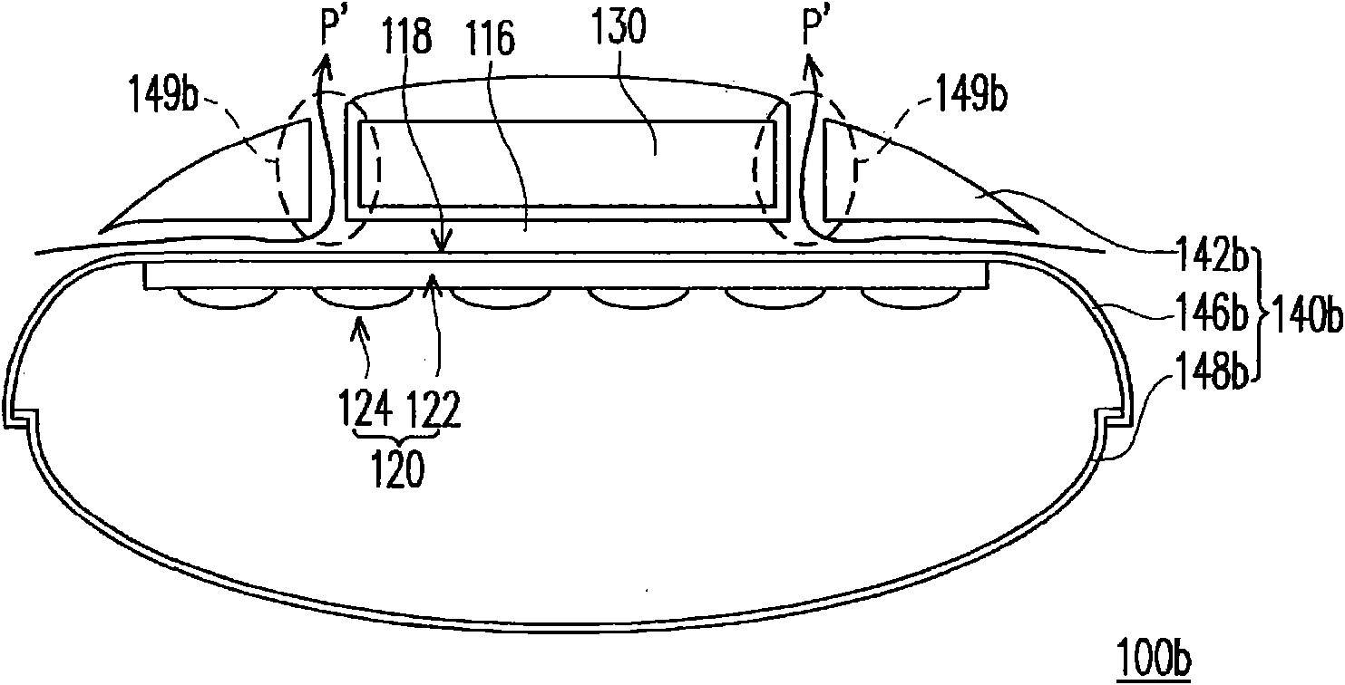
[0057] figure 2 It is a schematic cross-sectional view of the LED lighting device according to the second embodiment of the present invention. Please refer to figure 2 The LED lighting device 100 b of this embodiment is similar to the first embodiment, and it includes a casing 110 , an LED light source 120 and a power supply unit 130 . In this embodiment, the casing 110 is a road lamp housing 140b, and the street lamp housing 140b includes an upper lampshade 142b, a lower lampshade 146b, and a light-transmitting portion 148b.
[0058] In detail, the upper lampshade 142b defines the power receiving space 114 for accommodating the power supply unit 130, wherein the upper lampshade 142b has a plurality of gas convection holes 149b. One end of the lower lampshade 146b is connected to the other end of the upper lampshade 142b, wherein the first heat blocking passage 116 is located between the upper lampshade 142b and the lower lampshade 146b, and the gas convection hole 149b co...
no. 3 example
[0063] image 3 It is a schematic cross-sectional view of the LED lighting device according to the third embodiment of the present invention. Please refer to image 3 The LED lighting device 100c of this embodiment is similar to the LED lighting device 100b of the second embodiment. The board S, wherein the shroud S is connected with the upper lampshade 142b, and forms a second heat-blocking channel 116' between the shroud S and the upper lampshade 142b.
[0064] When the LED lighting device 100c is applied outdoors, the shroud S can shield the strong light from the hot sun, so as to prevent the power supply unit 130 from being directly exposed to sunlight, causing the power supply unit 130 to overheat and be damaged. In addition, the function of the second thermal isolation channel 116' is similar to that of the first thermal isolation channel 116, which can help the power supply unit 130 dissipate heat and insulate it. Generally speaking, the material of the shroud S incl...
PUM
 Abstract
Description
Claims
Application Information
 - R&D
- Intellectual Property
- Life Sciences
- Materials
- Tech Scout
- Unparalleled Data Quality
- Higher Quality Content
- 60% Fewer Hallucinations
Browse by: Latest US Patents, China's latest patents, Technical Efficacy Thesaurus, Application Domain, Technology Topic, Popular Technical Reports.
© 2025 PatSnap. All rights reserved.Legal|Privacy policy|Modern Slavery Act Transparency Statement|Sitemap|About US| Contact US: help@patsnap.com


