Micro phase delay measuring device for optical element based on laser feedback

A technology of laser feedback and optical components, which is applied in the field of laser measurement, can solve the problems of multi-instrument error and azimuth adjustment error, increase the complexity of the measurement system, and limit the measurement accuracy.

Inactive Publication Date: 2010-02-17
TSINGHUA UNIV
View PDF0 Cites 14 Cited by
  • Summary
  • Abstract
  • Description
  • Claims
  • Application Information

AI Technical Summary

Problems solved by technology

This increases the complexity of the measurement system. Due to the introduction of more instrument errors and azimuth adjustment errors in the measurement p

Method used


Image

  • Micro phase delay measuring device for optical element based on laser feedback
  • Micro phase delay measuring device for optical element based on laser feedback
  • Micro phase delay measuring device for optical element based on laser feedback

Examples


example

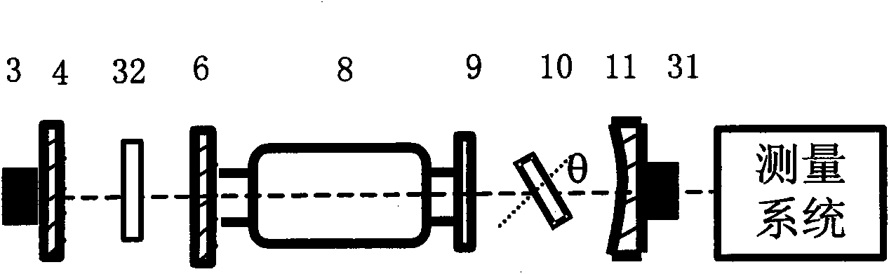
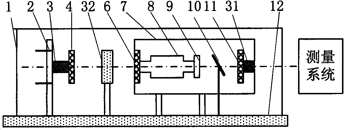
[0045] Example: such as figure 1 or figure 2 In the experimental system of the quarter-wave plate feedback, when the external cavity length changes, the two eigenpolarization states of the laser mode will alternately oscillate in two orthogonal directions, and the external cavity length changes for every λ / 4. The polarization state jumps once, and the two polarization states have the same duration within one laser intensity modulation period. When the feedback mirror 4 moves left and right along the laser axis under the impetus of the piezoelectric ceramic 3, the change frequency of the scanning voltage applied to the piezoelectric ceramic 3 can be adjusted so that the polarization state of the laser jumps once every 10 ms or so, so that The measurement of the frequency difference can be realized by scanning the interferometer so that two alternately oscillating polarization modes are simultaneously displayed on the oscilloscope.

[0046] First, observe the laser mode with...


PUM


Abstract

The invention relates to a micro phase delay measuring device for an optical element based on laser feedback, belonging to the technical field of laser measurement. The measuring device is characterized in that a double refraction laser feedback system comprising a 632.8nm He-Ne optical maser, an outer reflector and a quarter-wave plate is used to measure the phase delay of the optical element. The optical element to be measured is placed in a laser cavity, and the polarization state of the laser jumps in two orthogonal directions when the outer reflector moves left and right along the laser axis. With the polarization jump, the frequencies of the two eigenstates of the laser mode are different, and the frequency difference thereof is related to the size of phase delay of the laser cavity.The measurement of micro phase delay of the optical element can be realized by the principle. The measuring method of the micro phase delay of the optical element based on laser feedback and an implementation device thereof have the advantages of simple structure, easy assembly and adjustment, high measuring accuracy and low cost.

Description

technical field [0001] The invention relates to a laser feedback-based optical element micro phase delay measurement device, which belongs to the technical field of laser measurement. Background technique [0002] There are many factors that can cause phase anisotropy in optical components, such as: residual stress, birefringence, laser gain, and film non-uniformity. At present, there are many high-precision optical element phase delay measurement methods at home and abroad, but most of them are based on measuring quarter-wave plates, and there is no special method and device for measuring the small phase delay of optical elements. At present, the typical wave plate measurement methods are as follows. [0003] 1. Rotational extinction method [0004] The fast axis of a standard 1 / 4 wave plate is at a 45° angle to the polarization direction of the polarizer, and the fast axis of the measured 1 / 4 wave plate is in the same direction as the polarization direction of the polari...

Claims


Application Information

Patent Timeline
IPC IPC(8): G01J9/04
Inventor 费立刚张书练
Owner TSINGHUA UNIV
Why Eureka
Try Eureka