
Method for producing an acoustically resistive structure, resulting acoustically resistive structure and skin using one such structure

A manufacturing method and damping technology, which is applied to the manufacture of damping and sound-absorbing structures, can solve problems such as difficulty in positioning reinforced structures, reducing the effect of sound-absorbing treatment, and blocking fabric meshes, etc.

Active Publication Date: 2010-02-17
AIRBUS OPERATIONS (SAS)
View PDF0 Cites 15 Cited by
  • Summary
  • Abstract
  • Description
  • Claims
  • Application Information

AI Technical Summary

Problems solved by technology

[0026] Since the two components to be combined are no longer flat, the thickness of the adhesive can vary from a few centimeters to a millimeter, leading to non-uniformity in the connection between the reinforcing structure and the porous layers, increasing the risk of severe delamination
[0027] Additionally, excess adhesive tends to flow into the open or micro-perforated areas of the porous layer, which can block the fabric mesh used as the porous layer, greatly reducing the effectiveness of the sound dampening treatment
[0028] Finally, due to the complex shape of the components to be assembled, the cutting of the adhesive film and its positioning corresponding to the reinforcing structure are more difficult in operation to obtain a proper fit between the above-mentioned film and the opening area of ​​the above-mentioned reinforcement mechanism.

Method used


Image

  • Method for producing an acoustically resistive structure, resulting acoustically resistive structure and skin using one such structure
  • Method for producing an acoustically resistive structure, resulting acoustically resistive structure and skin using one such structure
  • Method for producing an acoustically resistive structure, resulting acoustically resistive structure and skin using one such structure

Examples


Embodiment Construction

[0042] The invention now described applies to the air intake of an aircraft propulsion plant. However, the invention can be applied to various parts of the aircraft that have been treated for sound dampening, such as the leading edge of a wing or any part that must withstand high temperatures, such as near the engine or near the blades of the engine

[0043] In the following description, whether it is frost or ice, it refers to ice and frost of various properties, various structures and thicknesses.

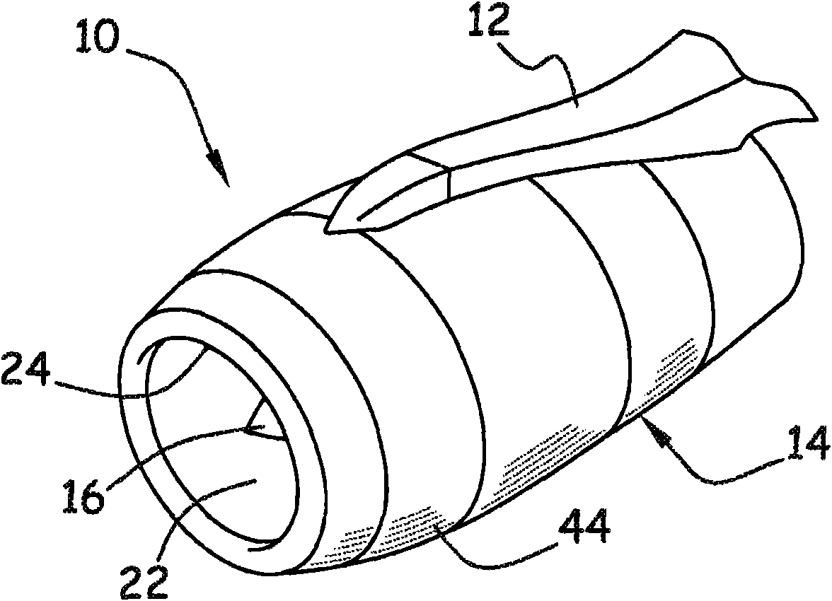
[0044] figure 1 A propulsion device 10 of an aircraft is shown, which is connected under the wing by struts 12 . However, this propulsion unit can also be connected to other areas of the aircraft.

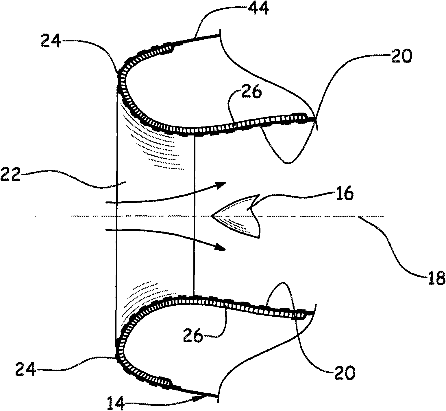
[0045] The propulsion means comprise an engine nacelle 14 in which are mounted power units in a generally concentric manner to drive an air intake mounted on a main shaft 16 . The longitudinal axis of the nacelle is identified by reference numeral 18 .

[0046] The nacelle 14 has ...


PUM


Abstract

The invention relates to a method for producing an acoustically resistive structure which can be mounted on a honeycomb structure such as to produce a skin for acoustical treatment, said acousticallyresistive structure including at least one porous layer (34) and at least one reinforcing structure (36) which are glued together. The invention is characterised in that the method comprises the following steps in which: an amorphous adhesive is applied to the at least one reinforcing structure (36), the reinforcing structure (36) is subsequently perforated or micro-perforated, and the at least one porous layer is applied against the surface of the reinforcing structure (36) that was coated with amorphous adhesive.

Description

technical field [0001] The present invention relates to the realization of a damping and sound-absorbing structure combining multiple layers, which can be made into a sound-absorbing treatment liner especially suitable for the surface of an aircraft engine nacelle to reduce the noise emitted by a turbojet engine placed in the above-mentioned engine nacelle . Background technique [0002] The propulsion unit of the aircraft consists of an engine nacelle in which is mounted substantially concentrically a power unit for driving an air intake unit mounted on its main shaft. [0003] The engine nacelle has an inner cavity wall that forms the air intake at the front end. The first part of the incoming airflow is called the primary airflow, which passes through the power plant to participate in combustion, and the second part of the airflow is called the secondary airflow. The gas unit is guided into an annular duct defined by the inner cavity wall of the engine nacelle and the ou...

Claims


Application Information

Patent Timeline
Patent Type & Authority Applications(China)
IPC IPC(8): G10K11/168F02C7/045
CPCF05C2253/22F02C7/24Y02T50/672Y02T50/67F02C7/045G10K11/172F05D2300/702Y02T50/60Y10T156/1056
Inventor 雅克·拉兰纳克里斯托夫·梅尼耶让·克里斯托夫·博西斯让·马克·普瓦诺纳克
Owner AIRBUS OPERATIONS (SAS)
Learn More