
Marine oily water disk aggregation and separation device

A technology for gathering and separating oil and sewage, applied in water treatment devices, ship parts, ship construction, etc., can solve problems such as emulsification, backflow of oil and sewage, and smaller dispersion of oil droplets

Inactive Publication Date: 2010-12-29
DONGTAI CITY DONGFANG MARINE FITTING
View PDF1 Cites 0 Cited by
  • Summary
  • Abstract
  • Description
  • Claims
  • Application Information

AI Technical Summary

Problems solved by technology

[0006] However, the unidirectional corrugated plate structure has many obvious deficiencies when it is used in the bilge oily sewage treatment and separation device: firstly, because ships sailing on the sea will always sway left and right, especially when encountering wind and waves, the maximum sway angle of the ship It can reach 45°, that is, one side of the ship may tilt 22.5°. In this case, the oily sewage in the oil-water channel of the one-way inclined corrugated plate will flow back, and the oil layer accumulated on the inclined plate will not only be unable to flow out of the inclined plate outlet. Float up, and the oil droplets will be further dispersed and smaller, or even emulsified, so that the oil-water separation cannot be achieved by gravity
At the same time, such reverse flow or forward flow also makes the separation device unable to work continuously and uninterruptedly.
Also, because the space of the ship is very precious, the oil-water separation device cannot occupy too much space, which makes the length of the oil-water separation channel very limited, which greatly restricts the effect of oil-water separation treatment, and even cannot realize the accumulation and separation of oil droplets

Method used


Image

  • Marine oily water disk aggregation and separation device
  • Marine oily water disk aggregation and separation device
  • Marine oily water disk aggregation and separation device

Examples


Embodiment Construction

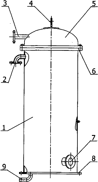
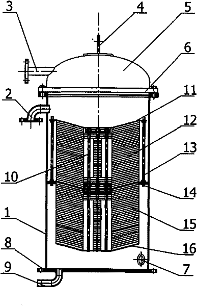
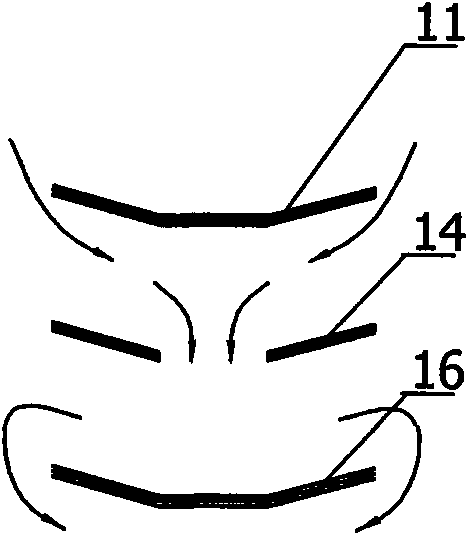
[0025] figure 1 In the marine oil-sewage stacked disc aggregation and separation device shown, the cylinder body 1 is cylindrical, and the material is made of high-quality carbon steel; the cylinder bottom plate 8 welded to the cylinder body 1 is a circular plate structure, and several mounting screw holes are provided on it. A sludge discharge port 9 is arranged on the bottom plate 8 of the cylinder, and the discharge port 9 is used to discharge sludge, particulate impurities, etc. deposited on the bottom of the cylinder to keep the cylinder relatively clean. The top of the cylinder body 1 is connected with a cylinder cover 5 through a connecting flange 6, and the cylinder cover 5 is in a spherical crown structure, and the waste oil discharge port 3 is arranged on the cylinder cover 5 in a spherical crown structure. Certainly cylinder body 1 can also adopt other shapes except adopting cylindrical cylindrical structure, and this cylinder cover 5 then should adopt other cylinde...


PUM


Abstract

The invention discloses a marine oily water disk aggregation and separation device, comprising a barrel body, wherein at least a first aggregation separator and a second aggregation separator are arranged in the barrel body; the first aggregation separator and the second aggregation separator are respectively positioned on the upper side and the lower side of a fluid guide hole plate; the periphery of the fluid guide hole plate are fixedly installed on the inner wall of the barrel body in a sealing manner; the middle position of the fluid guide hole plate is provided with a fluid guide through hole; the top end of the first aggregation separator is provided with a top part cover plate, and a gap is left between the periphery of the top part cover plate and the inner wall of the barrel body; the bottom part of the second aggregation separator is provided with a fluid guide blind plate, and a gap is left between the periphery of the fluid guide blind plate and the inner wall of the barrel body; and the first aggregation separator and / or the second aggregation separator comprise / comprises a plurality of mutually superposed ripple separating discs. The separation device has the advantages of simple structure, convenient maintenance and manufacturing, and ideal oil-water separation effect, and is particularly applicable to marine oily water separation.

Description

technical field [0001] The invention relates to the technical field of separation and treatment of oily sewage, in particular to a gravity separation device for ship oily sewage. Background technique [0002] With the rapid development of the world's shipping industry and the rapid increase of ship tonnage, ship waste has become a source of marine pollution that cannot be ignored, especially the bilge oily sewage such as ship oily ballast water, tank washing water, and engine room water. With great pressure, the discharge of oily sewage from ships has become an important factor in marine pollution. To this end, the International Maritime Organization and governments of various countries have successively issued a series of maritime laws and regulations to strictly control the pollution from ships. The Marine Environmental Protection Committee of the International Maritime Organization has also extended the regulation that the oil content of bilge water discharged by ships i...

Claims


Application Information

Patent Timeline
Patent Type & Authority Patents(China)
IPC IPC(8): B63J4/00
Inventor 陈海兵梅冬兴蔡晓幸马如中何丽君
Owner DONGTAI CITY DONGFANG MARINE FITTING
Learn More