Heat exchange compressor

A technology of heat compression and heat exchange tubes, which is applied in the field of heat exchange compressors and heating devices in the coating industry, which can solve the problems of exhaust emissions polluting the environment and dust blockage, and achieve the effect of long heat exchange distance and lower fuel cost.

Inactive Publication Date: 2010-02-24
童书开
View PDF1 Cites 1 Cited by
  • Summary
  • Abstract
  • Description
  • Claims
  • Application Information

AI Technical Summary

Problems solved by technology

[0004] The purpose of the present invention is to provide a heat exchange compressor that can use coal, coke or fuel oil as fuel, effectively reduce heating and heat exchange costs, and improve heat exchange efficiency. Heat exchange greatly improves the heat exchange efficiency, and can solve the defects of existing heating and heat exchange devices that are prone to dust blockage and exhaust pollution.

Method used


Image

  • Heat exchange compressor

Examples


Embodiment Construction

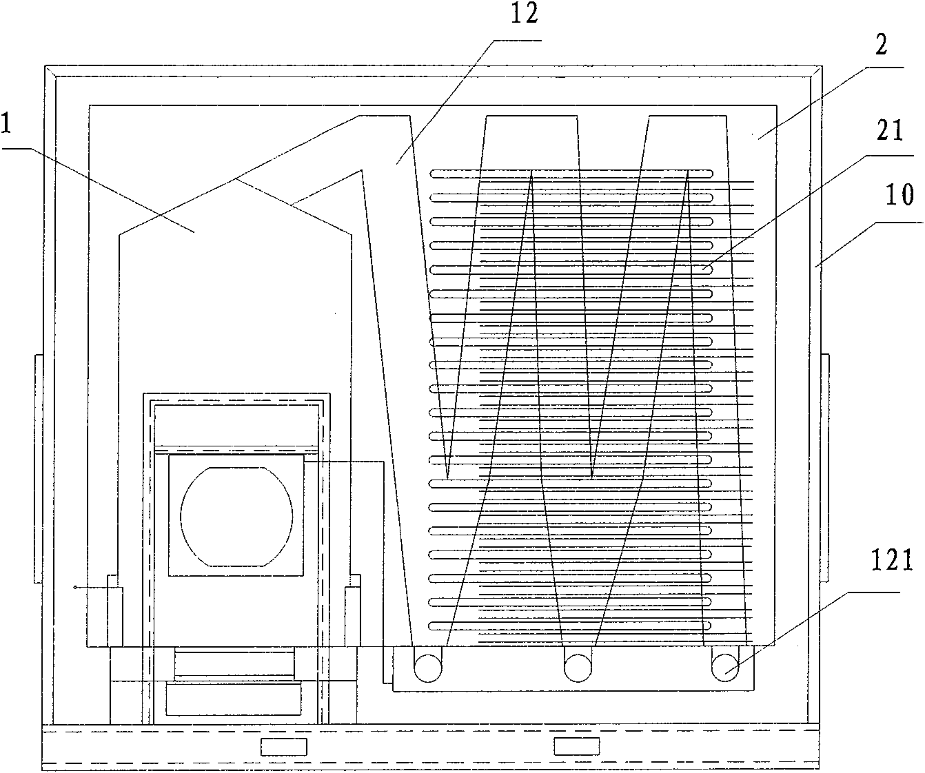
[0024] For the present invention, a preferred embodiment is now described in detail in conjunction with the drawings, as figure 1 As shown, the heat exchange compressor is mainly composed of a heating furnace 1, a heat exchange compression box 2, an air intake pipe 12, an exhaust pipe 5, an S-shaped heat exchange pipe 21 and an exhaust gas purification device. Its specific structure is as follows:

[0025] The heating furnace 1 is located on one side of the heat exchange compression box 2. The heating furnace 1 can realize automatic filling of fuel, and two intake pipes 12 are connected to the top of the heating furnace 1; the heating furnace 1 and the heat exchange compression box 2 are located in a closed shell 10 , between the heating furnace 1 and the heat exchange compression box 2 in the closed shell 10 are separated by a screen; the closed shell 10 is provided with several closed openings that can be opened and closed according to requirements;

[0026] Located on one s...


PUM


Abstract

The invention discloses a heat exchange compressor, comprising a heating furnace and at least one heat exchange compression box connected with the heating furnace. The heat exchange compressor is characterized in that the interior of the heat exchange compression box is provided with an intake pipe and an exhaust pipe, one end of the intake pipe is connected with the heating furnace, and the otherend is communicated with the exhaust pipe by at least three columns of S-shaped heat exchange pipes and at least three layers of S-shaped heat exchange pipes; and the intake pipe is bent in a continuous V shape, and a dust bin is arranged at the tail end of the lower part of each V-shaped bending. The heat exchange compressor efficiently settles the dust in the gas, cleans the pipeline to avoid blocking the pipeline by dust and has obvious energy-saving effect.

Description

technical field [0001] The invention relates to the technical field of heating for industrial heating, painting and other industries, in particular to a heat exchange compressor that uses coal, coke, and fuel oil as fuel, has low energy consumption and high heat exchange efficiency, and is especially suitable for the painting industry heating device. Background technique [0002] At present, the solidification or industrial heat exchange heating in the metal coating industry uses gas or fuel oil to heat the heating device, and the heated gas is used for heat supply. The heat production cost is high and the heat exchange efficiency is poor. Commonly used heating and heat exchange devices generally use a heat exchange tube located in the heat exchange room to heat the gas in the heat exchange room outside the heat exchange tube to achieve heat exchange. This type of heating device has many defects: First, the length of the heat exchange tube should not be too long. The length...

Claims


Application Information

Patent Timeline
Patent Type & Authority Applications(China)
IPC IPC(8): F24H3/00F24H3/08
Inventor 童书开
Owner 童书开
Why Eureka
Try Eureka