Mutual detection positioning system and method and plugging system

A positioning system, plug-in technology, applied in the direction of instruments, control mechanical energy, electric components, etc., can solve the problem of not being able to accurately grasp the output revolutions of the stepping motor, the insertion state of the linker, the number of drive signal pulses and the output The number of revolutions does not correspond to problems such as

Inactive Publication Date: 2010-02-24
NINGBO YINGMING ELECTRIC TECH +1
View PDF0 Cites 6 Cited by
  • Summary
  • Abstract
  • Description
  • Claims
  • Application Information

AI Technical Summary

Problems solved by technology

Normally, the number of pulses of the driving signal applied to the stepping motor corresponds to the output revolutions of the stepping motor, that is, a certain proportional relationship is satisfied. Due to the wear and tear of the motor itself, it often happens that the number of pulses of the drive signal of the stepping motor does not correspond to the number of output revolutions. At this time, it is impossible to accurately grasp the output revolutions of the stepping motor simply by controlling the number of pulses of the externally applied signal.
In addition, because the above-mentioned plug-in system works in an open-loop situation, during the process of inserting the connector into or pulling out from the swap hole, the insertion status of the connector cannot be known simply by the number of signal pulses applied from the outside, for example , if the linker has been inserted to the maximum of the exchange hole, continue to apply the pulse drive signal to the stepper motor, the linker will still only maintain the original state, because the entire plug-in system is in a linkage state, so the output revolutions of the stepper motor have already is zero, but this situation cannot be known only from the number of pulses of the driving signal that is still continuously applied by the outside world
Similarly, when a fault occurs, the system cannot detect the fault because the insertion status of the linker cannot be known simply through the number of signal pulses applied from the outside.

Method used


Image

  • Mutual detection positioning system and method and plugging system
  • Mutual detection positioning system and method and plugging system
  • Mutual detection positioning system and method and plugging system

Examples


Embodiment Construction

[0015] In order to make the purpose, technical solutions and advantages of the embodiments of the present invention clearer, the technical solutions in the embodiments of the present invention will be clearly and completely described below in conjunction with the drawings in the embodiments of the present invention. Obviously, the described embodiments It is a part of embodiments of the present invention, but not all embodiments. Based on the embodiments of the present invention, all other embodiments obtained by persons of ordinary skill in the art without creative efforts fall within the protection scope of the present invention.

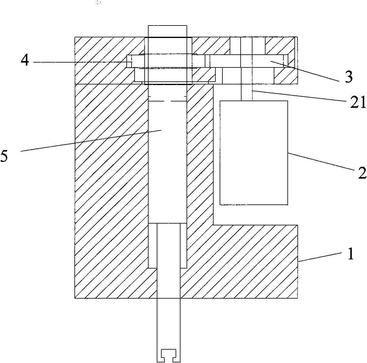
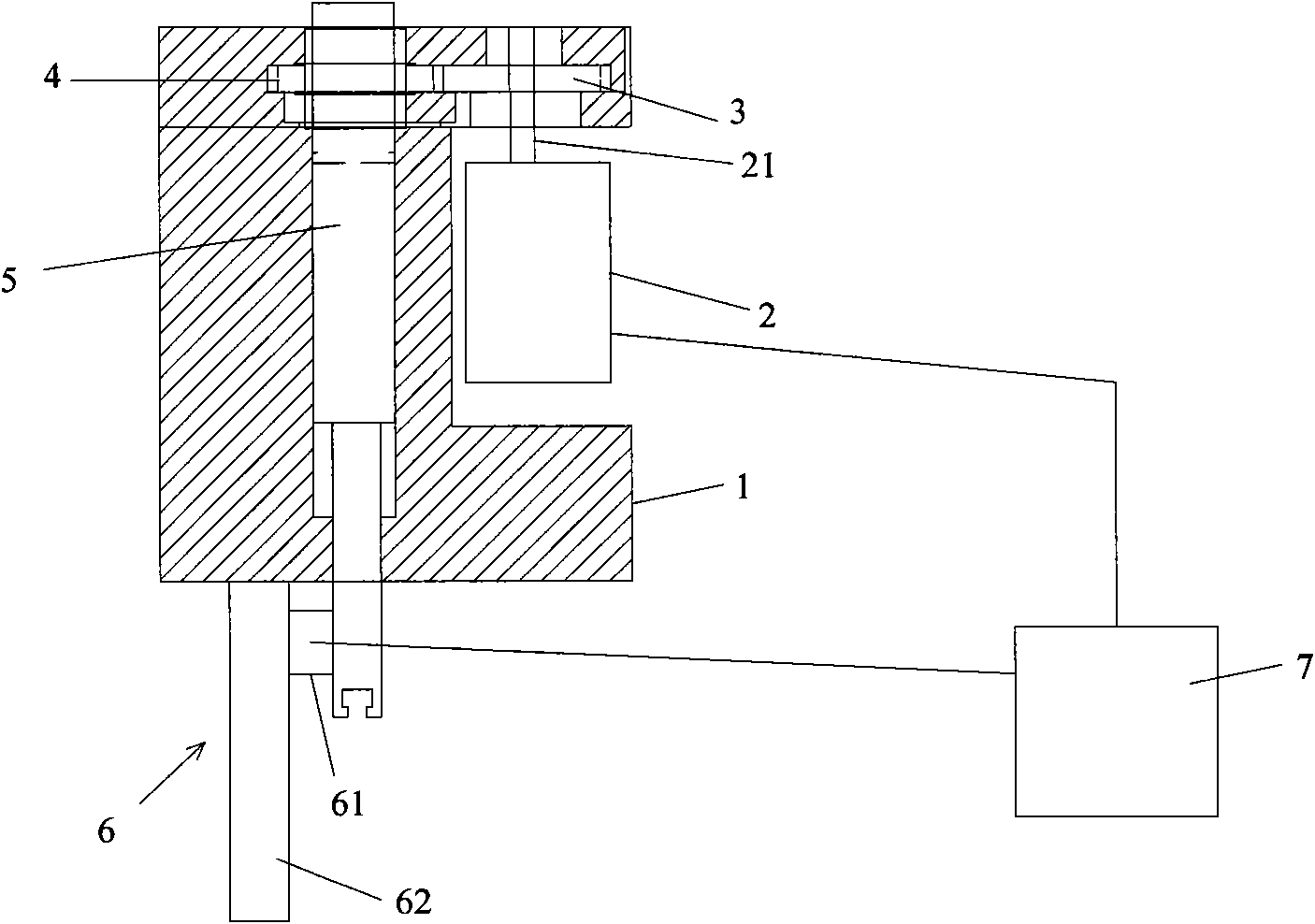
[0016] The first embodiment of the present invention provides a mutual detection positioning system, such as figure 2 As shown, the mutual detection positioning system includes a grating linear displacement sensor 6, the laser head part 61 of the grating linear displacement sensor 6 is fixedly installed on the side of the plugger 5, and the grati...


PUM


Abstract

The invention provides a mutual detection positioning system, a mutual detection positioning method and a plugging system. The mutual detection positioning system comprises a raster straight-line displacement sensor and a controller. When a plugging device moves up and down in a vertical direction, the raster straight-line displacement sensor detects the displacement of the plugging device, and outputs pulse output signals corresponding to the displacement of the plugging device. A connecting part is arranged between the plugging device and a stepping motor arranged in a worktable, and the stepping motor drives the plugging device to move up and down through the connecting part. The controller is connected with the stepping motor and a rotary raster encoder through circuits, and used for comparing the pulse number N1 of driving signals input to the stepping motor and the pulse number N2 of output signals of the raster straight-line displacement sensor and recognizing the working condition of the puller. The embodiment of the invention can recognize the current state of the plugging device, and can also detect the fault of the system.

Description

technical field [0001] The invention relates to the field of optical fiber communication equipment, in particular to a mutual detection and positioning system and method of a screw and an encoder and a corresponding plugging system. Background technique [0002] In optical fiber switching equipment, it is often necessary to insert or pull out the linker at one end of the external line fiber or cable fiber into the switch hole on the switch board. In order to control the lifting and plugging actions of the linker, you can use figure 1 The plugging system shown in does the above for the linker. The plugging system includes a workbench 1, a stepper motor 2 is installed in the workbench 1, the first transmission gear 3 is fixedly connected with the power output end 21 of the stepper motor 2, so that the stepper motor 2 can drive the first transmission The gear 3 rotates horizontally, the first transmission gear 3 meshes with the second transmission gear 4, the inserter 5 penet...

Claims


Application Information

Patent Timeline
Patent Type & Authority Applications(China)
IPC IPC(8): G02B6/38G01B11/02G01D5/36H02K7/116H02K11/00H02K37/24
Inventor 范骏行戎家铨
Owner NINGBO YINGMING ELECTRIC TECH
Why Eureka
Try Eureka