Double-frequency imaging fractal dipole antenna

A dipole antenna and dipole technology, applied in the direction of antenna, resonant antenna, mid-position feed between antenna terminals, etc., to achieve the effect of small size, simple structure, and good radiation characteristics

Inactive Publication Date: 2013-07-24
XIAMEN UNIV
View PDF0 Cites 0 Cited by
  • Summary
  • Abstract
  • Description
  • Claims
  • Application Information

AI Technical Summary

Problems solved by technology

At present, there is no related technology that combines the three-half curve fractal patch, the application of the mirror structure, and the photonic bandgap structure to make a dual-frequency dipole antenna and apply it in the 2.4GHZ and 5.8GHZ working frequency bands of the RFID system. to report

Method used


Image

  • Double-frequency imaging fractal dipole antenna
  • Double-frequency imaging fractal dipole antenna
  • Double-frequency imaging fractal dipole antenna

Examples


Embodiment Construction

[0027] The present invention will be further described below in conjunction with embodiment and accompanying drawing.

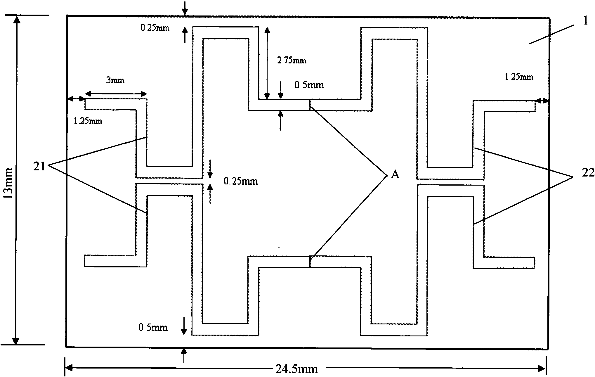
[0028] see figure 1, the present invention is provided with double-sided copper-clad epoxy resin substrate 1, substrate 1 is FR4 substrate, and one side of the copper-clad layer is 2 pairs of dipole arms that are identical and mirror-symmetrical, that is, the left dipole antenna radiation patch 21 and the right dipole antenna radiating patch 22. The dipole arm structure is a first-order three-half fractal curve (3 / 2curve) structure. The dimensions of the substrate 1 are: the length is 24.5mm±0.25mm, the width is 13mm±0.25mm, and the thickness is 0.8mm±0.25mm. The structural dimensions of the left dipole antenna radiation patch 21 and the right dipole antenna radiation patch 22 are as follows: figure 1 shown. Be provided with disconnection gap A on the symmetrical center line of left dipole antenna radiation patch 21 (being left dipole arm) and right dipol...


PUM


Abstract

The invention relates to a dipole antenna, in particular to a double-frequency imaging fractal dipole antenna with small size, large bandwidth, lower echo loss and universal radiation characteristic. The double-frequency imaging fractal dipole antenna is provided with a basal plate, wherein both sides of the basal plate are covered by metal layers, two pairs of dipole arms are symmetrically arranged on one metal layer in an imaging mode; either dipole arm is a dipole antenna radiation patch in a 3 / 2 fractal curve structure; and the other metal layer is in a rectangular array photon band gap structure. The invention can achieve the aim of miniaturizing an RFID antenna so that the RFID antenna can be put in an RFID label or a reader-writer; and the invention also has the advantages of smallsize, wide bandwidth, good universal radiation characteristic, simple structure, simple manufacture process, low cost, easy integration, and the like and can satisfy the concrete requirements of an RFID application system for antennae.

Description

technical field [0001] The invention relates to a dipole antenna, in particular to a dual-frequency image fractal dipole antenna. Background technique [0002] Radio Frequency Identification (Radio Frequency Identification, abbreviated as RFID) is a non-contact automatic identification technology realized by radio frequency communication that began to emerge in the 1990s. RFID tags have the characteristics of small size, large capacity, long life, and reusability. They can support fast reading and writing, non-visual identification, mobile identification, multi-target identification, positioning and long-term tracking management. Combined with other technologies, it can be used in logistics, manufacturing, public information services and other industries to achieve efficient management and operation and reduce costs. With the continuous improvement and maturity of security soft information-related technologies, the RFID series industry will become an emerging high-tech indu...

Claims


Application Information

Patent Timeline
Patent Type & Authority Patents(China)
IPC IPC(8): H01Q1/38H01Q9/16H01Q13/08H01Q5/01H01Q5/10
Inventor 周建华罗勇黄李琳枊青胡秀丽林斌游佰强
Owner XIAMEN UNIV
Why Eureka
Try Eureka