Method and device for controlling robots for welding workpieces

A robot and workpiece technology, applied in the direction of using optical devices, general control systems, program control, etc., can solve the problems of unable to identify the height of the profile, unable to identify the starting and ending cutting edges of the profile incision, etc., to achieve great flexibility. Effect

Active Publication Date: 2010-02-24
费劳恩霍弗应用技术研究院 +1
View PDF6 Cites 20 Cited by
  • Summary
  • Abstract
  • Description
  • Claims
  • Application Information

AI Technical Summary

Problems solved by technology

The limitation of this method is that neither the profile height, i.e. the length of the vertical seam, nor the cutouts of the profile and the different starting and ending cutting edges can be identified

Method used


Image

  • Method and device for controlling robots for welding workpieces
  • Method and device for controlling robots for welding workpieces
  • Method and device for controlling robots for welding workpieces

Examples


Embodiment Construction

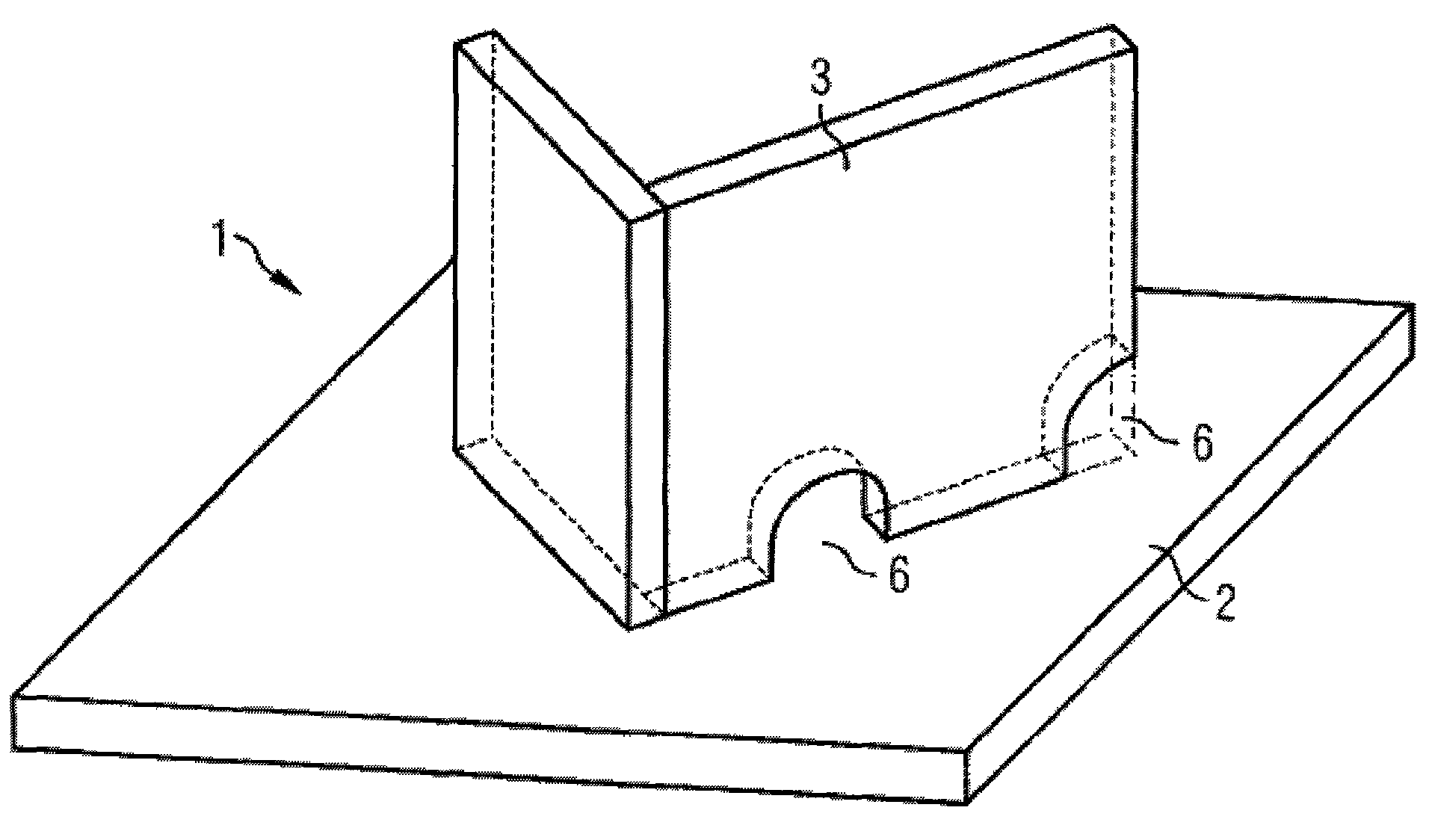
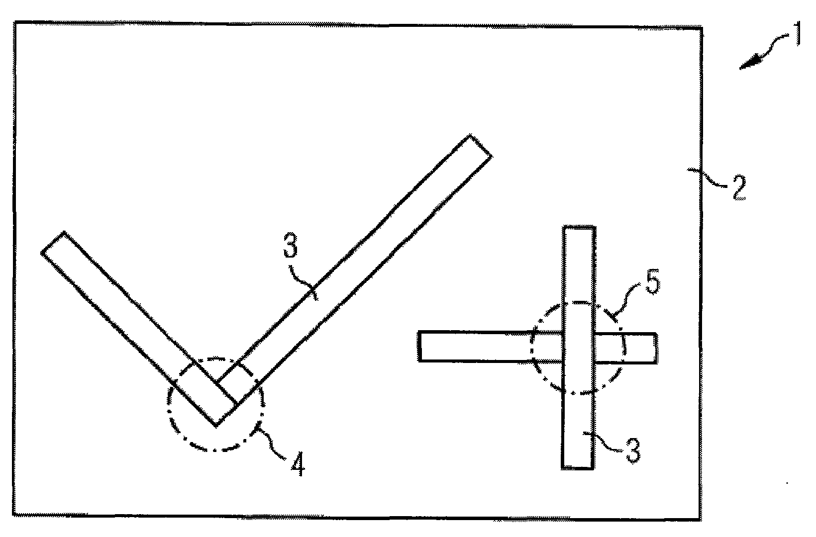
[0016] exist figure 1 and figure 2 Two micropanels 1 are shown in a simplified manner in , generally comprising steel plates 2 commonly used in shipbuilding, and having steel profiles 3 spot welded to the steel plates 2, the surface area of ​​which generally does not exceed 3m x 16m. The micropanels shown are constructed in a schematic manner only, generally the steel plate 2 is provided with burn-throughs 6 and undercuts, and the number of profiles 3 is also greater.

[0017] These micropanels 1 , ie profiles 3 and steel plates 2 , are welded by a robot, such as an articulating arm robot, with the aim of controlling said welding in an automatic manner. For this, a welding line in the x-y plane must be defined between the profile 3 and the steel plate 2 and a welding line in the z direction must be defined between the profiles 3 .

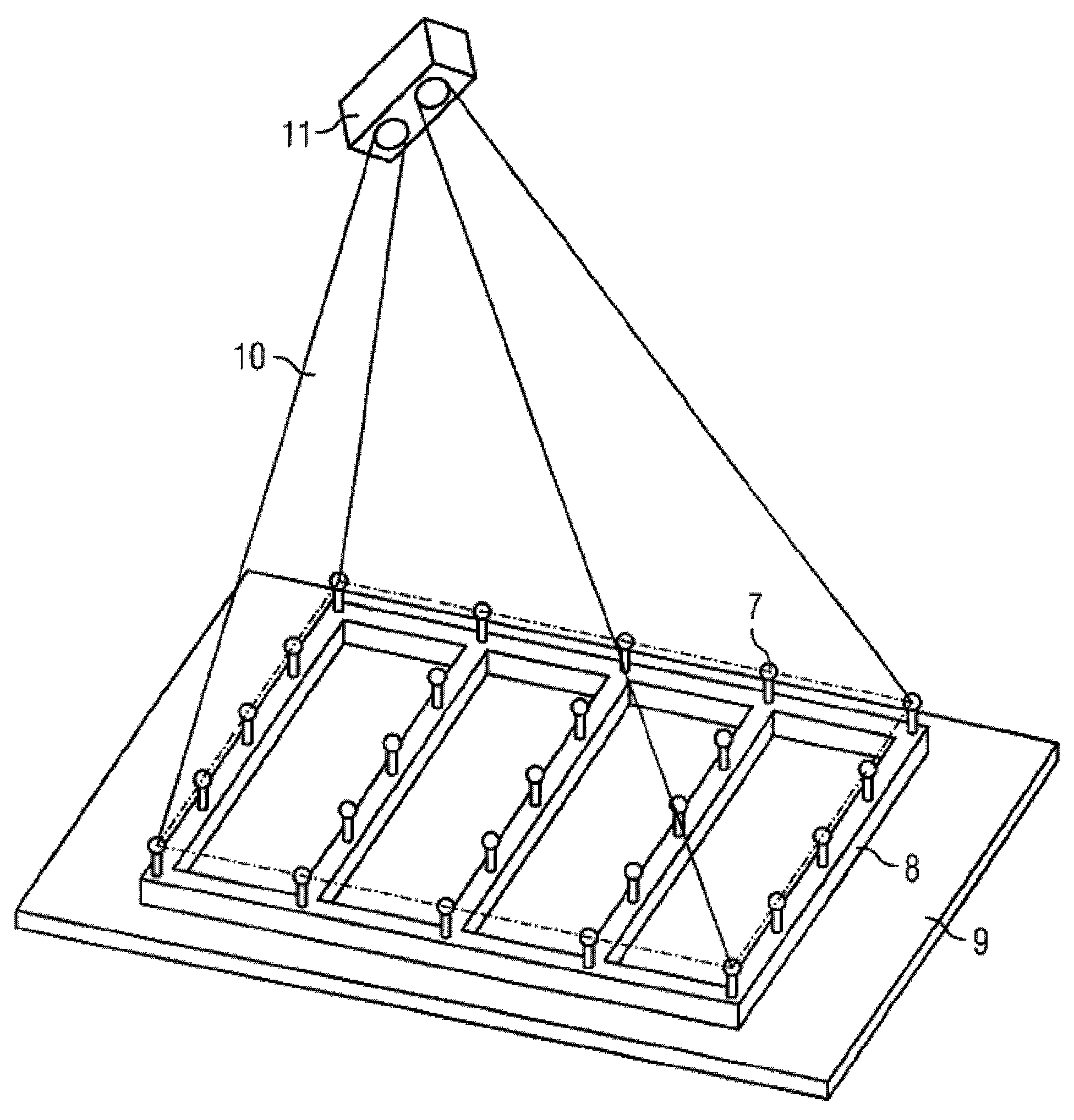
[0018] Therefore, in this embodiment, a 3D laser scanner is used to scan the placed micro-panel 1, and according to the size of the working are...


PUM


Abstract

The invention relates to a method for controlling robots for welding three-dimensional workpieces, comprising the following steps: positioning and tacking profiles (3) to a plate (2) in order to formthe workpiece to be welded (1), depicting the workpiece by means of a three-dimensional imaging system in the form of three-dimensional pixels, determining the geometric data of the plate and profiles, including the allocation of cutouts and final cutting shapes from the three-dimensional pixels, determining the weld seam data from the geometric data while considering the profile placement lines and the contact lines of profiles, allocating the weld seam data to parameterizable specifications for the weld plan into stored predefined movement patterns of the robot, and into commands for the control of the welding process.

Description

technical field [0001] The invention relates to a method for controlling a robot for welding three-dimensional workpieces. Background technique [0002] Micro panels comprising steel plates and reinforcing profiles welded to the steel plates are used in shipbuilding. Initially, different types of reinforcement profiles are spot welded to the steel sheet and subsequently welded by an articulating robot or portal welding cell. The profiles are distinguished by different profile shapes, dimensions and end cut edges, which can be arranged in any way on the steel plate. However, especially in the case of small piece counts, such as for micropanels in shipbuilding, the kinematic programming of welding robots for orbital welding has a disproportionately high complexity overall, unless it is an automated manufacturing process. [0003] Currently, almost all programming methods for welding three-dimensional workpieces in shipbuilding are based on acquiring corresponding CAD data an...

Claims


Application Information

Patent Timeline
Patent Type & Authority Applications(China)
IPC IPC(8): G05B19/42
CPCG05B2219/37567G05B19/4207G05B2219/37009B23K31/02G01B21/042G05B2219/45104G01B11/2518G05B2219/37555G05B2219/36248B23K9/0256G06T7/0057G06T7/521G05B19/42
Inventor 马丁·克里斯托弗·万纳亚历山大·崔西乌维·普弗莱特斯切尔
Owner 费劳恩霍弗应用技术研究院
Why Eureka
Try Eureka