Atmospheric plasma chemical processing method of WC and SiC optical molding molds

A plasma and chemical processing technology, applied in the direction of manufacturing tools, glass forming, glass pressing, etc., can solve the problems of reduced mold service life, sub-surface damage, low processing efficiency, etc., to reduce system costs, efficient removal, Effects of reduced precision and stiffness requirements

Active Publication Date: 2010-03-03
HARBIN INST OF TECH
View PDF0 Cites 41 Cited by
  • Summary
  • Abstract
  • Description
  • Claims
  • Application Information

AI Technical Summary

Problems solved by technology

[0004] The purpose of the present invention is to solve the problems of low processing efficiency, poor surface quality, subsurface damage, and reduced service life of the mold after the optical molding mold of the current SiC and WC materials is processed by grinding and polishing processes. Problem, provide an atmospheric plasma chemical processing method for WC and SiC optical molding dies

Method used


Image

  • Atmospheric plasma chemical processing method of WC and SiC optical molding molds
  • Atmospheric plasma chemical processing method of WC and SiC optical molding molds
  • Atmospheric plasma chemical processing method of WC and SiC optical molding molds

Examples


specific Embodiment approach 1

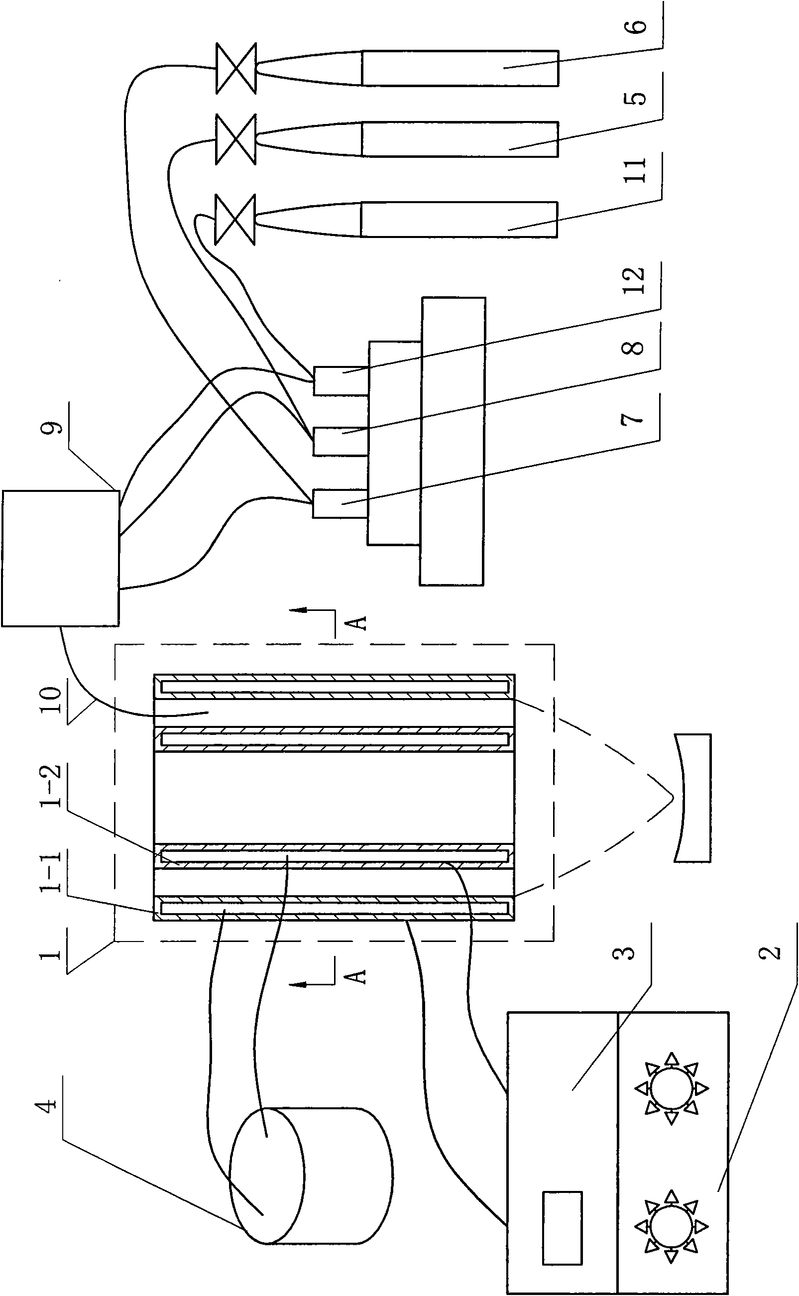
[0030] Specific implementation mode one: the following combination figure 1 , Image 6 Describe this embodiment mode, the device that realizes the method of the present invention is by plasma generator 1, radio frequency power supply 2, impedance matcher 3, cooling water pump 4, plasma gas bottle 5, reaction gas bottle 6, first flow controller 7, the first Two flow controllers 8, a gas mixing chamber 9, a gas delivery pipe 10, an oxygen bottle 11 and a third flow controller 12 are formed,

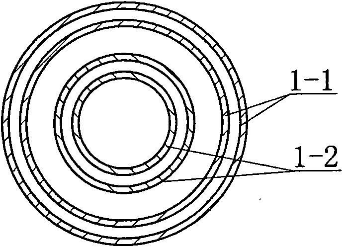
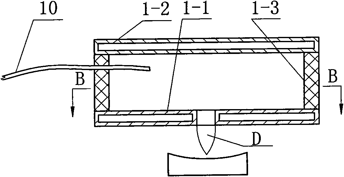
[0031] The plasma generator 1 includes a cathode 1-1 and an anode 1-2 that are parallel or coaxially set, the outer surfaces of the cathode 1-1 and the anode 1-2 are respectively coated with an insulating film, and the cathode 1-1 and the anode 1-2 The internal cavities of the cooling water pump 4 are respectively connected to an outlet of the cooling water pump 4 through pipelines, and the cathode 1-1 and the anode 1-2 are respectively connected to the negative electrode and the positive ...

specific Embodiment approach 2

[0064] Specific embodiment two: the difference between this embodiment and embodiment one is that in step three, the flow rate of plasma gas is selected to be 20 liters per minute, and the flow ratio of reaction gas and oxygen to plasma gas is 1:10; step In the fourth step, the power of the radio frequency power supply 2 reaches 800W, and rough molding is performed on the WC or SiC optical molding die. Other components and connections are the same as those in Embodiment 1.

specific Embodiment approach 3

[0065] Specific embodiment three: the difference between this embodiment and embodiment two is that step three is repeated, the flow rate of the selected plasma gas is 20 liters per minute, and the flow ratio of the reaction gas and oxygen to the plasma gas is 1:20; Fourth, make the power of the radio frequency power source 2 reach 500W, and carry out precision molding processing on the WC or SiC optical molding die. Other components and connections are the same as those in Embodiment 2.


PUM


Abstract

The invention relates to an atmospheric plasma chemical processing method of WC and SiC optical molding molds, which belongs to the atmospheric plasma chemical processing methods of the optical molding molds. The atmospheric plasma chemical processing method can solve the problems that the grinding and polishing technology which is used for processing after processing and forming of the optical molding molds made of SiC and WC materials has the disadvantages of low processing efficiency, poor surface quality, damage of a sub-surface layer and short service life of the molds. The method comprises the steps of: introducing a mixture of plasma gas, reaction gas and oxygen into space between a cathode and an anode of a plasma generator, imposing radio frequency power signals on the cathode andthe anode, producing the plasma discharge between the two electrodes, then placing the surface to be processed of the WC or SiC optical molding mold in a plasma jet region for carrying out chemical reaction and realizing the optical surface processing of the optical molding molds made of the SiC and WC materials. The method is used for carrying out the optical processing on the surfaces of the WCand SiC optical molding molds.

Description

technical field [0001] The invention relates to an atmospheric plasma chemical processing method for WC and SiC optical molding dies. Background technique [0002] Compared with various plastic lenses, optical lenses made of glass materials are more and more widely used due to their optical properties such as high refractive index and low thermal expansion coefficient. It can be used to manufacture various lenses, prisms and filters used in military and civilian optical instruments; to manufacture optical fiber coupler lenses for optical communication; to manufacture light-gathering aspheric lenses for optical discs; to manufacture digital cameras, digital video cameras, Lenses for mobile phones, various aspheric surfaces for viewfinders, and even diffractive optical lenses. The annual global demand for this type of optical parts reaches hundreds of millions, which cannot be met by traditional grinding and polishing processes. Production and processing of large quantities o...

Claims


Application Information

Patent Timeline
Patent Type & Authority Applications(China)
IPC IPC(8): C04B41/91C03B11/06
Inventor 王波金会良张强
Owner HARBIN INST OF TECH
Why Eureka
Try Eureka