Kinematics calibration method of measurement robot

A technology for measuring robots and kinematics, applied in the field of measurement, can solve the problems of difficult automation, laborious, time-consuming, etc., and achieve the effect of long installation time, low cost and high cost

Inactive Publication Date: 2010-03-03
DALIAN MARITIME UNIVERSITY
View PDF0 Cites 33 Cited by
  • Summary
  • Abstract
  • Description
  • Claims
  • Application Information

AI Technical Summary

Problems solved by technology

Existing calibration usually requires the use of three-coordinate measuring machines, laser trackers and other equipment. The entire process requires a lot of manual intervention, which is time-consuming and laborious, and it is difficult to automate

Method used


Image

  • Kinematics calibration method of measurement robot
  • Kinematics calibration method of measurement robot
  • Kinematics calibration method of measurement robot

Examples


Embodiment Construction

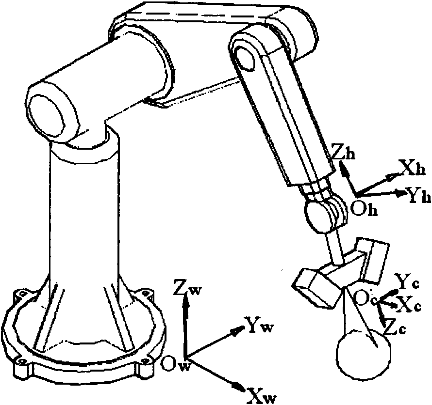
[0009] Industrial robots generally have an open-loop motion structure, and the angle value of each axis can be determined through an angle measuring device. By establishing the corresponding homogeneous equation on each axis and constructing the motion model of the robot, the end position and posture of the robot can be determined. Determining the homogeneous transformation matrix of each axis of the robot requires four parameters: connecting rod length a, connecting rod offset d, connecting rod torsion angle α, and shaft rotation angle θ. By multiplying these homogeneous matrices together, the pose of the end of the robot can be determined. In this article, the structured light sensor is installed at the end of the robot. Suppose the pose matrix of the sensor coordinate system relative to the robot end coordinate system is H, and the pose matrix of the sensor coordinate system relative to the robot base coordinate system

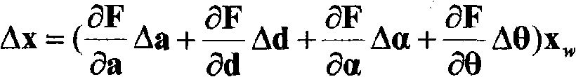
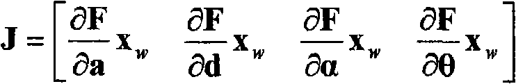
[0010] T=F(a, d, α, θ, H)

[0011] Since the connecting...


PUM


Abstract

The invention relates to a kinematics calibration method of a measurement robot; the method mainly aims at computing kinematics parameter error of an industrial robot with a distance-measurement sensor; the method comprises a distance-measurement sensor, an industrial robot and a sphere with known radius, wherein the distance-measurement sensor is arranged at the end of the industrial robot, the sphere with known radius is used as a target and is arranged in a measurable range of a measuring head; the steps of kinematics parameter calibration are: firstly, the robot drives the sensor to measure spherical surface with more than seven poses, measurement data and pose data of the robot are recorded, and then, a centered spherical surface that measurement data is converted to a base coordinatesystem of the robot and spherical radius fixation are taken as a constraint condition, the kinematics parameter error of the robot is computed by nonlinear optimization, so as to realize simultaneouscalibration of a kinematics model and connecting relation of the sensor and the robot.

Description

Technical field [0001] The invention relates to the field of measurement technology, and to be precise, a method for kinematics calibration of a measurement robot. Background technique [0002] Robots were born in the 1960s. After decades of development, robotics technology has already matured. Robots with vision functions are mainly used in industrial fields such as automobiles, electronics, and machinery manufacturing. Among them, the most widely used are robot hand-eye coordination functions, such as grasping robots, assembly robots, and arc welding robots. Robot vision has already had a mature technology application in the processing and manufacturing industry. [0003] With the development of robot technology, the application of robots in measurement has also received more and more attention. Robot measurement has the characteristics of online, flexibility, and high efficiency, and can achieve 100% measurement of parts. Therefore, it is particularly suitable for process and...

Claims


Application Information

Patent Timeline
Patent Type & Authority Applications(China)
IPC IPC(8): G01B21/00G01B11/00
Inventor 马孜李爱国胡英
Owner DALIAN MARITIME UNIVERSITY
Why Eureka
Try Eureka