
Movable core type squirt cut device applied to water-assisted injection molding

A technology of injection molding and movable core, applied in the field of movable core type water needle device, can solve the problems of high cost of water needle, complicated process, difficult to realize industrialized production, etc., and achieve the effect of improving the molding effect, good workmanship and easy standardization.

Inactive Publication Date: 2010-03-10
ZHEJIANG UNIV
View PDF0 Cites 6 Cited by
  • Summary
  • Abstract
  • Description
  • Claims
  • Application Information

AI Technical Summary

Problems solved by technology

This type of water needle adopts advanced powder metallurgy technology. The water needle is covered with small holes, which can effectively solve the problem of melt blockage and greatly increase the injection flow rate. There have been cases of using this type of water needle for testing abroad, but this The cost of water injection is relatively high, and the process is relatively complicated, so it is still difficult to realize industrial production
[0006] In addition, it can realize the functions of water inlet and drainage at the same time, and can be applied to molds of different specifications. The structure is simple, compact, and the water needle with good versatility is still rarely reported at home and abroad.

Method used


Image

  • Movable core type squirt cut device applied to water-assisted injection molding
  • Movable core type squirt cut device applied to water-assisted injection molding
  • Movable core type squirt cut device applied to water-assisted injection molding

Examples


Embodiment Construction

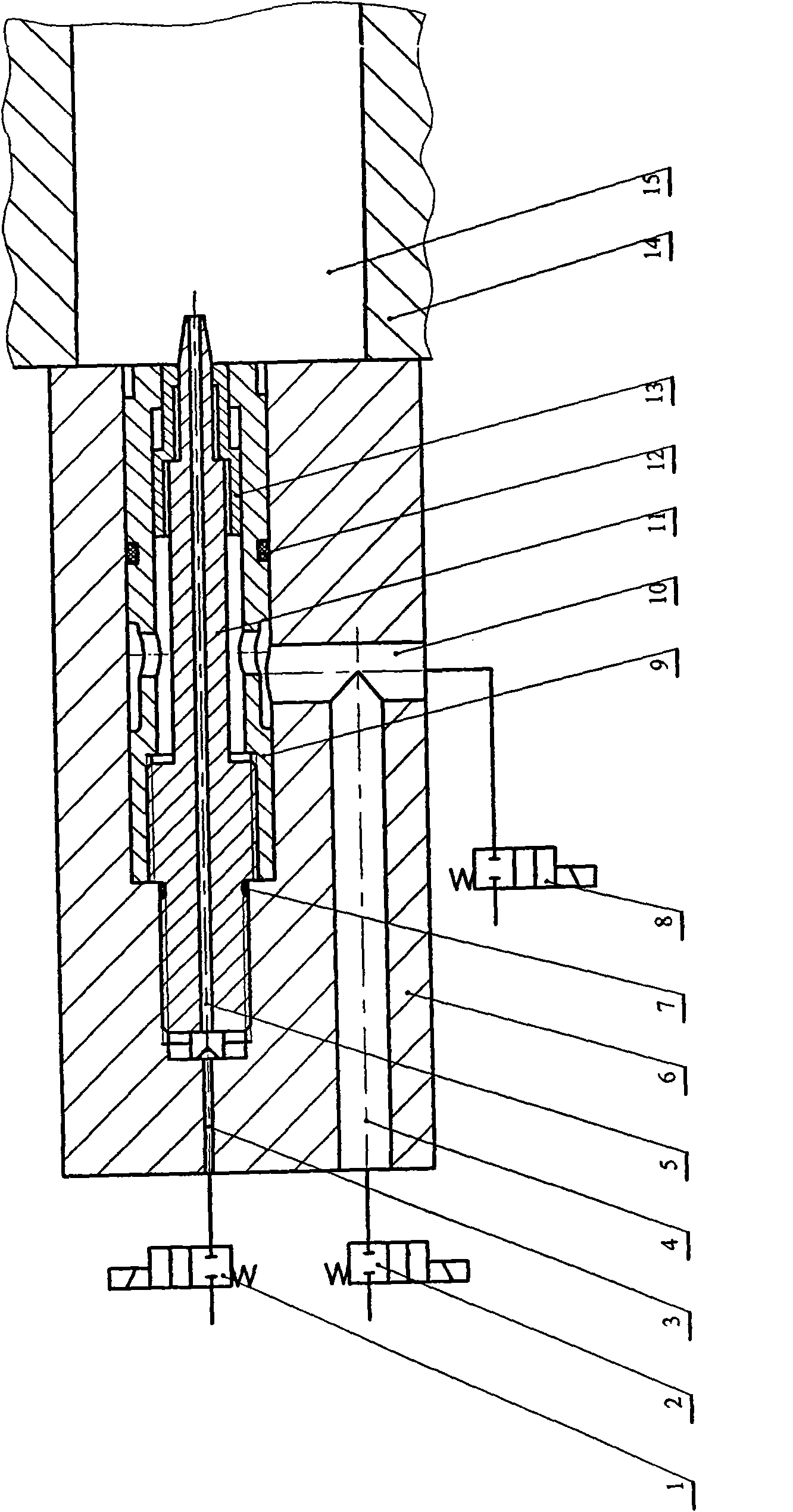
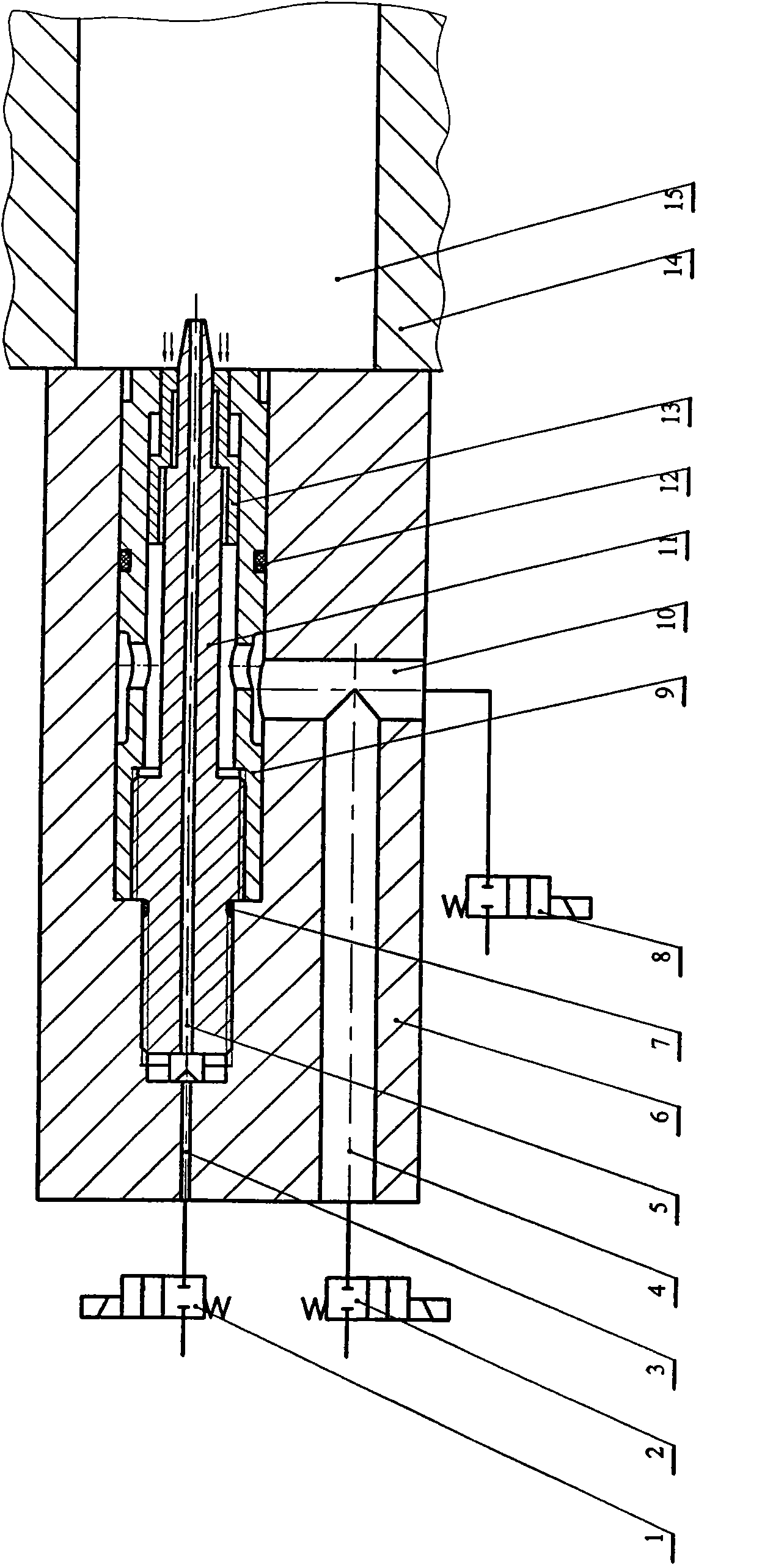
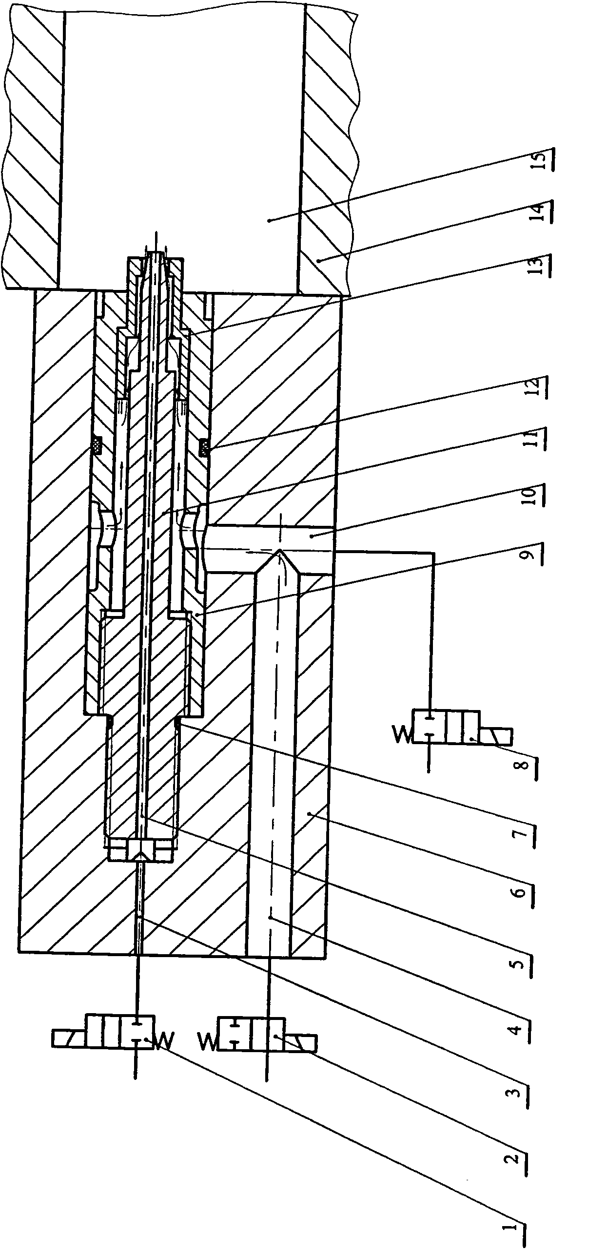
[0025] like figure 1 As shown, the present invention includes a water needle installation block 6, a movable core type water needle, an air pressure electromagnetic switch valve 1 and two water pressure electromagnetic switch valves 2, 8; wherein:

[0026] 1) The water needle installation block 6 is axially opened with a water inlet flow channel 4, an air inlet flow channel 3, and a movable core-type water needle installation hole with a small end connected to the air intake flow channel 3 and a large one at the other end. The water needle installation block 6 There is a drainage channel 10 in the inner radial direction, and the drainage channel 10 is connected with the water inlet channel 4 and the large movable core type water needle installation hole at the right end. Connected to the water inlet channel 4, the second water pressure electromagnetic switch valve 8 is connected to the drain channel 10;

[0027] 2) Movable core type water needle: including needle sheath 9, ne...


PUM


Abstract

The invention discloses a movable core type squirt cut device applied to water-assisted injection molding, comprising a squirt cut cover, a squirt cut body, a movable core, a gaseous core and a seal element, wherein the squirt cut cover is provided with an inlet opening, an air inlet and a movable core mating hole; the squirt cut body is fixed in the squirt cut cover, the movable core and the gapof a squirt cut body ring form an injection water flow path; the movable core moves to open and close the gap to control on and off of the flow path; the position of the movable core is determined bythe differential pressure of water inlet pressure and pressure in an outlet mould; a through hole is arranged in the squirt cut body, the gaseous core is arranged in the hole; and the gaseous core andthe through hole form a gap passage in a fit clearance manner. The invention can realize a water-assisted injection molding water inlet, air inlet and drainage function. The flow path is automatically switched on and off according to differential pressure of pressure water inlet and pressure in mould cavity to prevent high-temperature fusant in the mould cavity from entering the squirt cut. The squirt cut adjusts the maximum through-flow gap between the movable core and the squirt cut body by adjusting the relative position of the squirt cut body and the squirt cut cover according to different specifications of the mould, thus the squirt cut has adjustable through-flow capability and favourable popularity.

Description

technical field [0001] The invention relates to a fluid-assisted injection molding device, in particular to a movable core type water needle device applied to water-assisted injection molding. Background technique [0002] Water-assisted injection molding technology is a new molding technology in the field of injection molding. It is mainly used to manufacture hollow or semi-hollow plastic products with complex inner cavity shapes. It eliminates the core mold and directly injects high-pressure water into the high-temperature melt quickly. A hollow cavity is formed, and the fluid is kept under pressure for cooling. Compared with the traditional gas-assisted molding technology, water-assisted injection molding has the advantages of good product quality, low material consumption, and short production cycle. However, due to the late start of water-assisted molding technology, key components and technologies are still immature. As a key component of the water-assisted injection...

Claims


Application Information

Patent Timeline
IPC IPC(8): B29C45/57
Inventor 周华陈英龙杨华勇
Owner ZHEJIANG UNIV
Learn More