Quick test device and method for performances of trough type solar thermal collector

A trough-type solar energy and testing device technology, which is applied in the testing of machines/structural components, measuring devices, optical instrument testing, etc., can solve the problems of inconsistency of test results, high requirements for meteorological parameters of steady-state testing technology, and high cost. Achieve the effects of easy implementation, rapid measurement of heat collection performance, and simple device structure

Active Publication Date: 2010-03-10
深圳市汇元佳实业发展有限公司
View PDF0 Cites 23 Cited by
  • Summary
  • Abstract
  • Description
  • Claims
  • Application Information

AI Technical Summary

Problems solved by technology

The steady-state test technology has high requirements on meteorological parameters, so it can only be tested indoors with optical equipment.
However, in practice, solar collectors work outdoors, and the actual environment will inevitably cause the test results to be inconsistent with the test results simulated indoors.
Therefore, there is an urgent need for a means of testing outdoors. At present, there are related test devices abroad, such as the trough solar test device of ENEA in Italy, but the test equipment is more complicated and expensive, and it cannot achieve the purpose of rapid measurement.

Method used


Image

  • Quick test device and method for performances of trough type solar thermal collector
  • Quick test device and method for performances of trough type solar thermal collector
  • Quick test device and method for performances of trough type solar thermal collector

Examples


Embodiment Construction

[0026] The present invention will be described in further detail below in combination with specific embodiments.

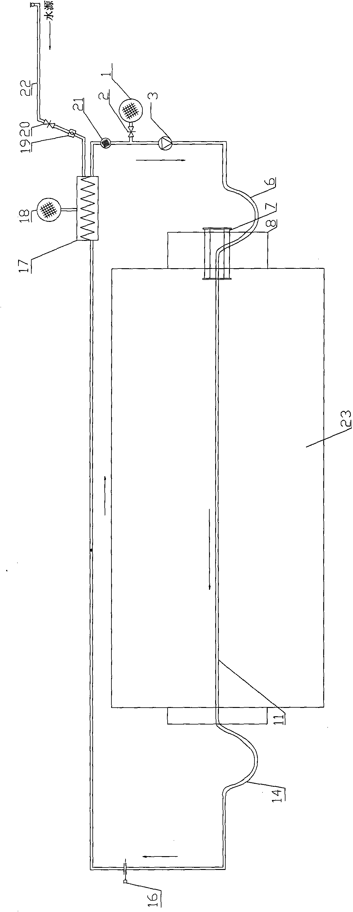
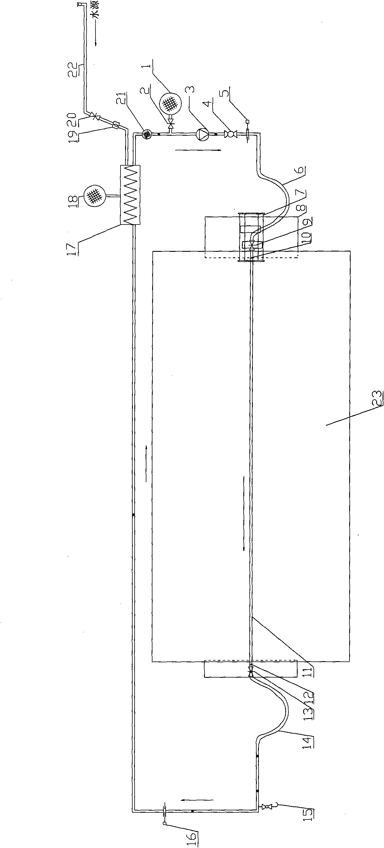
[0027] see figure 1 As shown, this preferred embodiment comprises oil tank 1, the valve 2 that is arranged on the oil tank port, oil pump 3, metal hose 6, heat collector 23, heat exchanger 17, steam tank 18, expansion container 21, water pipe 22, and The heat collector is fixed in the same direction as the direct radiation meter (not shown in the figure), the heat collecting tube 11, the metal bracket support 8 for supporting the heat collector, the solar tracking system 7 for driving the heat collector 23, and the solar tracking system 7 connected to the heat collecting tube 11 The pressure gauge 16 between the heat exchanger 17, the oil pump 3, the metal hose 6, the heat collecting pipe 11, the metal hose 14, the pressure gauge 16, the heat exchanger 17, and the expansion vessel 21 are sequentially connected with pipelines to form a circulation loop. The water ...


PUM


Abstract

The invention discloses a quick test device for performances of a trough type solar thermal collector, which comprises a fuel tank, a valve arranged at the port of the fuel tank, a fuel pump, a thermal collector, a heat interchanger, a vapor tank, an expansion tank, a water pipe and a direct radiometer which is fixed with the thermal collector in the same direction, wherein the focusing point of the thermal collector is provided with a thermal collecting pipe; the fuel tank is filled with heat conducting fuel; the thermal collector, the heat interchanger and the expansion tank are connected bypipelines in sequence to form a loop; the thermal collecting pipe is connected on the left of the valve, and the expansion tank is connected on the right thereof; and the water pipe and the vapor tank are respectively connected at the inlet and the outlet of the heat interchanger. The quick test device has the advantages of simple and easily-implemented structure and capability of realizing quicktest of performances of the thermal collector. The invention also discloses a quick test method for the performances of the trough type solar thermal collector.

Description

【Technical field】 [0001] The invention relates to a heat energy testing device and a testing method, in particular to a rapid testing device and a method for the performance of a trough solar heat collector. 【Background technique】 [0002] Existing test methods for solar collectors are based on steady-state testing techniques, and the test content includes the steady-state or quasi-state instantaneous efficiency of the collector and the heat loss coefficient of the collector. The steady-state test technology has high requirements on meteorological parameters, so it can only be tested indoors with optical equipment. However, in practice, solar collectors work outdoors, and the actual environment will inevitably cause the test results to be inconsistent with the test results simulated indoors. Therefore, there is an urgent need for a means that can be tested outdoors. At present, there are related test devices abroad, such as the trough solar test device of ENEA in Italy, but...

Claims


Application Information

Patent Timeline
Patent Type & Authority Applications(China)
IPC IPC(8): G01M11/00G01M11/02
Inventor 周佣仔赵华平彭启成贺冬枚
Owner 深圳市汇元佳实业发展有限公司
Why Eureka
Try Eureka