Switch reluctance motor double master switch power converter master switch fault diagnosis method

A technology of switched reluctance motors and power converters, which is applied to the measurement of electrical variables, circuit breaker testing, instruments, etc., can solve the problem that the system cannot judge the type and location of the fault, and achieve rapid diagnosis, good effect, Robust Effect

Active Publication Date: 2010-03-10
CHINA UNIV OF MINING & TECH
View PDF0 Cites 44 Cited by
  • Summary
  • Abstract
  • Description
  • Claims
  • Application Information

AI Technical Summary

Problems solved by technology

However, the switched reluctance motor power converter with dual main switches in each phase will have short-circuit faults on the upper main switch tube, short-circuit faults on the lower main switch tube, short-circuit faults on both the upper main switch tube and the lower main switch tube, and short-circuit faults on the upper main switch tube. When an open circuit fault occurs, the lower main switch tube has an open circuit fault, and both the upper main switch tube and the lower main switch tube have an open circuit fault, it is necessary to locate the fault and distinguish the fault type in order to take corresponding fault tolerance measures; The switched reluctance motor power converter of the main switch has no fault detection and fault location functions, so when the power converter fails, the system cannot judge the fault type and fault location

Method used


Image

  • Switch reluctance motor double master switch power converter master switch fault diagnosis method
  • Switch reluctance motor double master switch power converter master switch fault diagnosis method
  • Switch reluctance motor double master switch power converter master switch fault diagnosis method

Examples


Embodiment Construction

[0016] Embodiments of the present invention will be further described below in conjunction with the accompanying drawings:

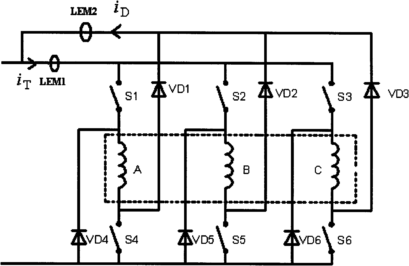
[0017] Taking a three-phase switched reluctance motor as an example with two main switching power converters per phase, as figure 1 As shown, a current sensor LEM1 is set on the DC bus of the main switch to detect the total current i of the main switch on the DC bus T ; Set a current sensor LEM2 on the DC bus of the freewheeling diode to detect the total current i fed back by the freewheeling diode on the DC bus D , the direction of the arrow in the figure is the positive direction of the current. Connect the wires of the two current sensors to the receiver to obtain the total current signal of the main switch and the total current signal fed back by the freewheeling diode; the receiver adopts a computer or a single-chip microcomputer or a digital signal processor Or oscilloscopes or virtual instruments. The current detected by the two current sensors ...


PUM


Abstract

The invention provides a switch reluctance motor double master switch power converter master switch fault diagnosis method. A current sensor LEM1 is arranged on the master switch current circuit (DC)busand and is used for testing the total current of the main switch on the DC bus, a current sensor LEM2 is arranged on the free-wheeling diode DC bus and is used for testing the total current feedback by the free-wheeling diode on the DC bus, the wires of the two current sensors are connected with a receiver to obtain the total current signal of the master switch and the total current signal fedback by the free-wheeling diode. The invention can be used for judging that short trouble occurs to both the upper master switch tube and the lower master switch tube and open fault occurs to both theupper main switch tube and the lower main switch tube, and can be used for carrying out fault location, thus having convenient fault-tolerant control, and wide application prospects.

Description

technical field [0001] The invention relates to a fault diagnosis method for a main switch of a switched reluctance motor power converter, which is suitable for a switched reluctance motor power converter with two main switches per phase of various phases. Background technique [0002] The switched reluctance motor power converter with dual main switches per phase is a unipolar power converter, which supplies unipolar current to the switched reluctance motor. Switched reluctance motor power converters are prone to failures in harsh environments such as coal mines and aerospace. Since the switched reluctance motor power converter with dual main switches for each phase can make the phases on the motor magnetic circuit and system circuit of the switched reluctance motor system independent of each other, when the switched reluctance motor system fails, it is convenient to adopt fault-tolerant measures to realize switching Reluctance motor systems operate with high reliability i...

Claims


Application Information

Patent Timeline
Patent Type & Authority Applications(China)
IPC IPC(8): G01R31/327G01R19/00
Inventor 陈昊
Owner CHINA UNIV OF MINING & TECH
Why Eureka
Try Eureka