Motor control method based on DCS system
A DCS system, motor control technology, applied in the direction of motor control, control system, electrical components, etc., can solve the problems of time-consuming, low level of human-computer interaction settings, reduce fault finding time, etc., to improve safety and increase the amount of information. and maintainability, the effect of improving readability
- Summary
- Abstract
- Description
- Claims
- Application Information
AI Technical Summary
Problems solved by technology
Method used
Image

Examples
Embodiment Construction
[0020] Attached below Figure 1 to Figure 6 The present invention is described in further detail with embodiment:
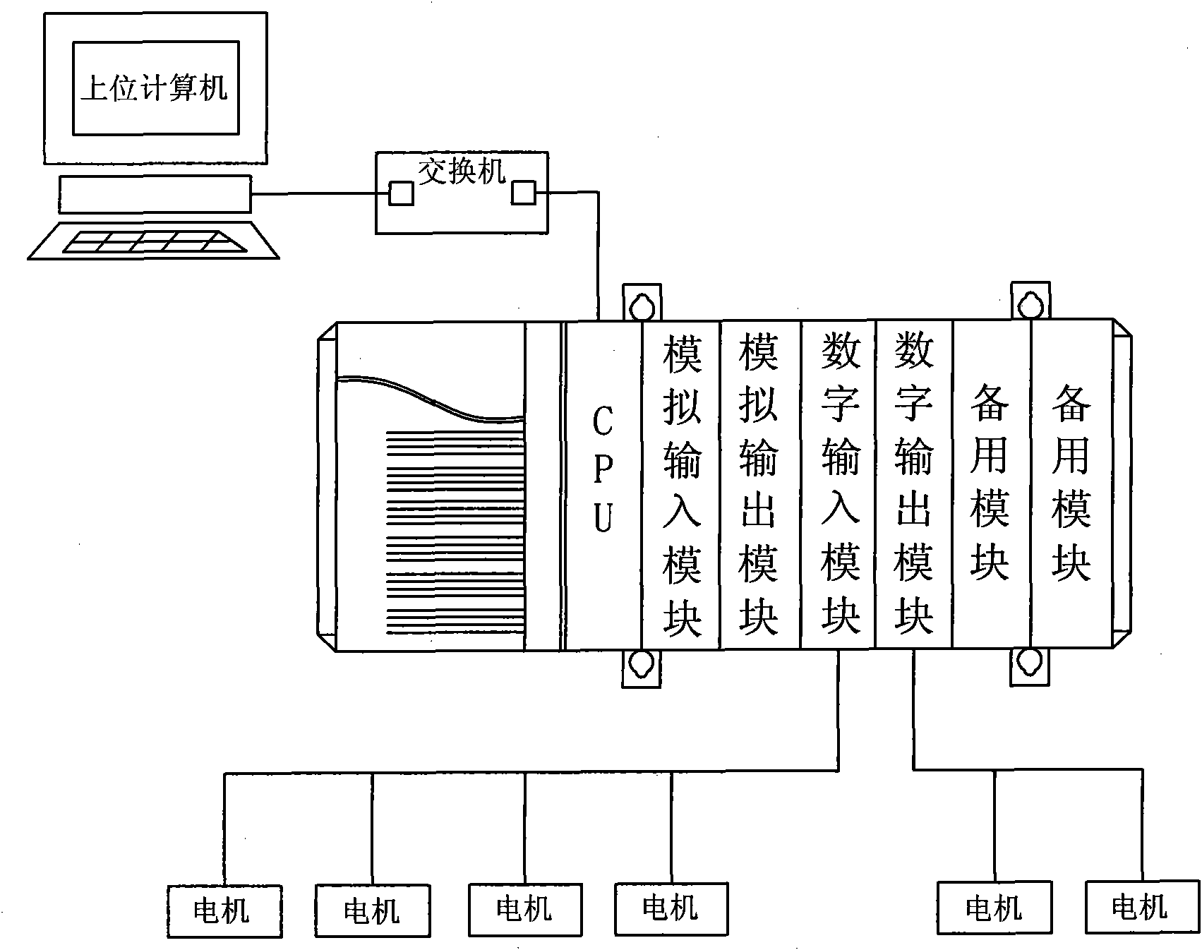
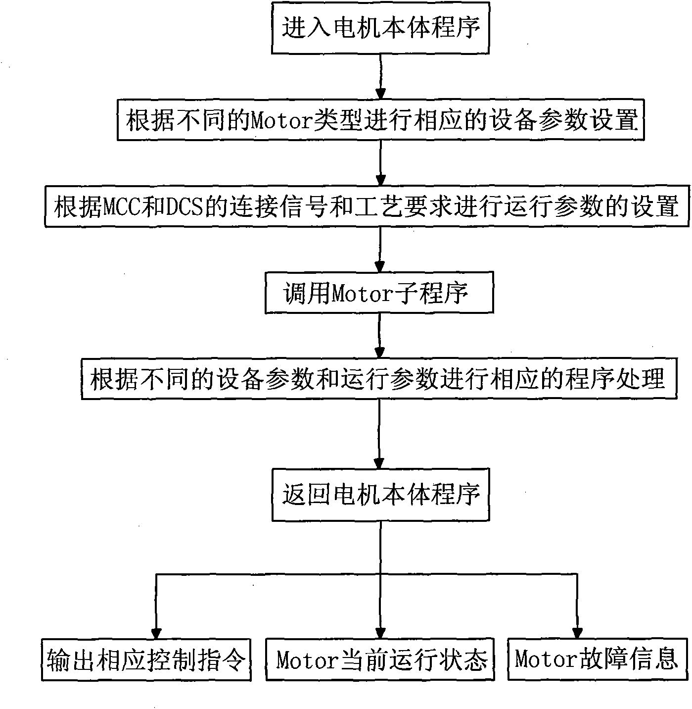
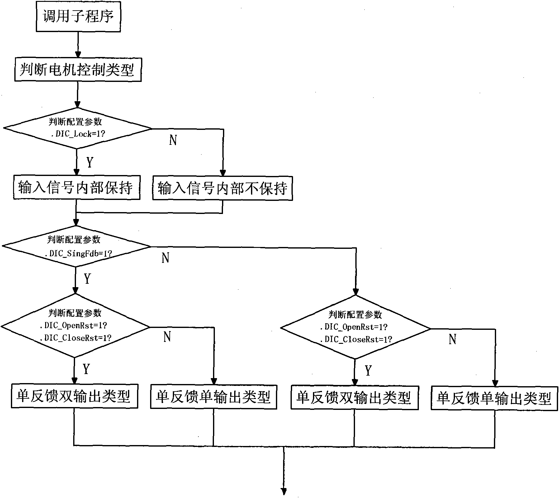
[0021] Embodiments The motor control method based on the DCS system is to set the motor operation and control parameters by the computer through network communication to realize the operation and control of the motor. The DCS system includes a control motor and a host computer connected to the control motor. The host computer There is a switch between the control motor and the control motor. There are several different types of motors connected to the control motor, and a standard motor module is installed inside the control motor. After setting the parameters, call the motor subroutine, realize signal processing and control of different types of motors by calling the standard motor module, and then return to the main body program that controls the motor after the subroutine processing is completed, and at the same time output the corresponding Control commands,...
PUM
 Abstract
Description
Claims
Application Information