
Embedded stirring friction spot welding method

A friction stir and embedded technology, which is applied in welding equipment, non-electric welding equipment, metal processing equipment, etc., can solve the problems of affecting the service life of stirring tools, poor appearance of joints, wear of "needle" parts, etc.

Inactive Publication Date: 2010-03-17
XI AN JIAOTONG UNIV
View PDF0 Cites 35 Cited by
  • Summary
  • Abstract
  • Description
  • Claims
  • Application Information

AI Technical Summary

Problems solved by technology

[0015] The purpose of the present invention is to solve the traditional friction stir spot welding of dissimilar metals (such as Al / steel, Al / stainless steel, Al / Cu, Ti / steel, etc.) There are two technical problems: one is the severe wear problem of the tool: when one of the second base metal 2 is steel, the steel has severe wear on the "needle" part of the stirring tool, which seriously affects the service life of the stirring tool and normal welding The process is carried out smoothly; the second is the problem of poor flatness of the appearance of the joint: the remaining keyhole is deep and the flash is large after the "needle" is pulled out, and the flatness is poor

Method used


Image

  • Embedded stirring friction spot welding method
  • Embedded stirring friction spot welding method
  • Embedded stirring friction spot welding method

Examples


Embodiment Construction

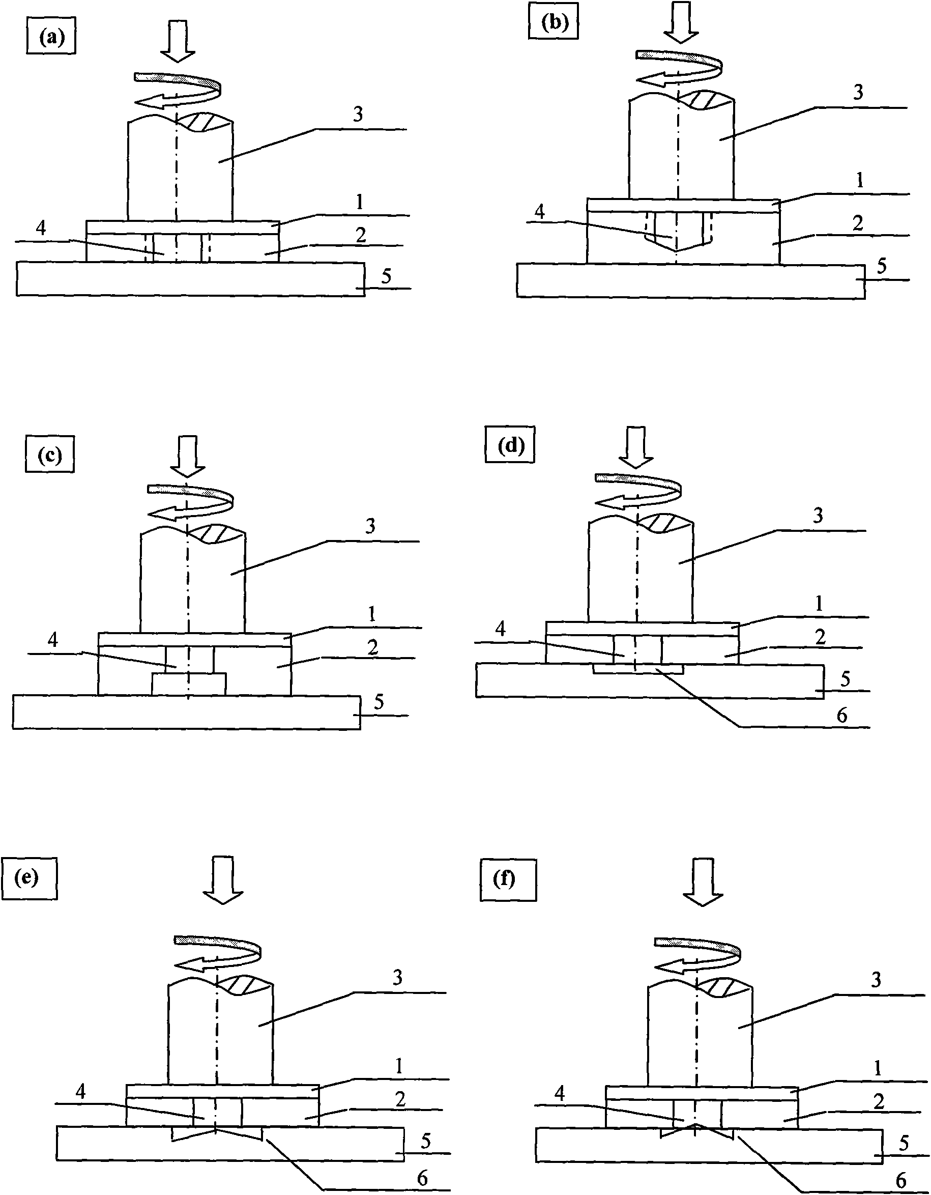
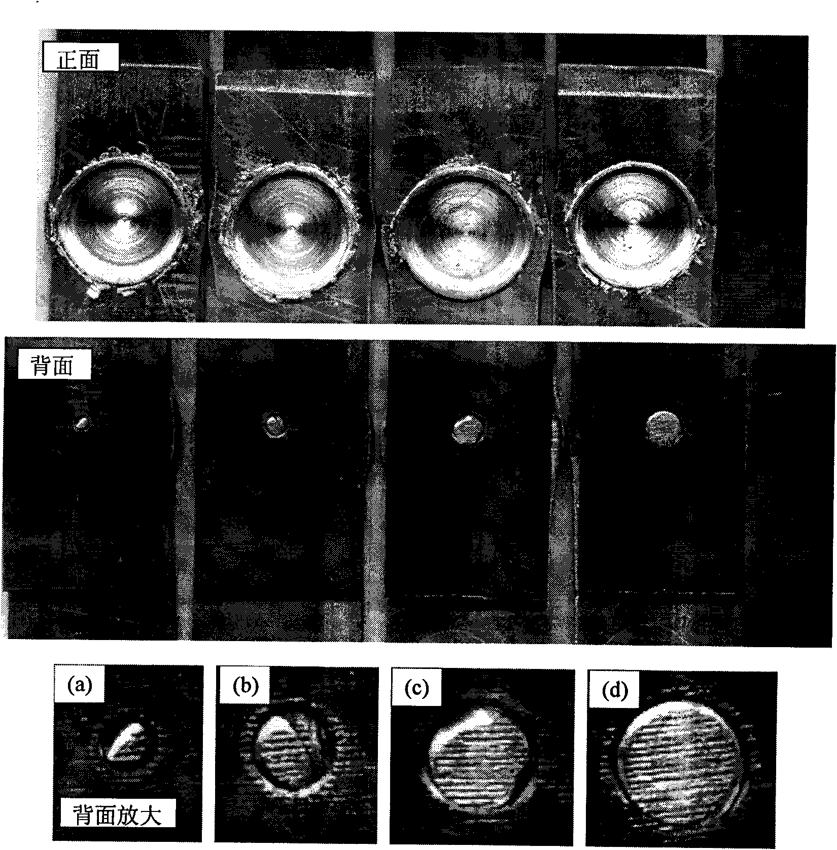
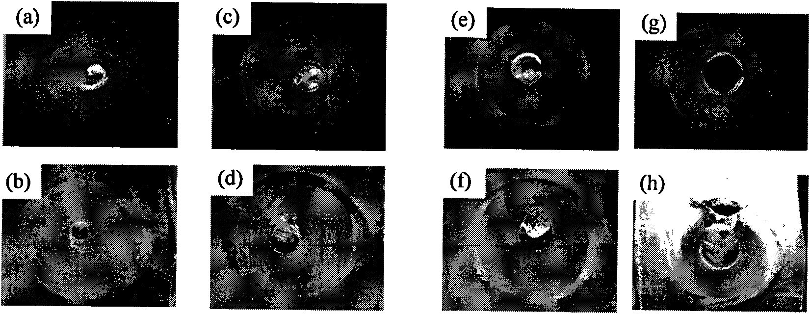
[0043] The invention discloses an embedded friction stir spot welding method, which is especially suitable for the overlapping connection of aluminum (magnesium) and high melting point, relatively hard dissimilar metal materials (such as carbon steel, stainless steel, copper, titanium, etc.). An example (taking the economical aluminum plate and steel plate as an example) is given below to illustrate how to implement embedded friction stir spot welding, and introduce the test results of the welded joint performance to prove the practicability of the present invention.

[0044] An embedded friction stir spot welding method, firstly, a hole 4 is provided on the second base material 2; then, the first base material 1 is placed on top of the harder second base material 2, and the second base material 1 is assembled in an overlapping form A base material 1 and a second base material 2; finally, rotate the needle-free stirring head 3 and make the needle-free stirring head 3 contact th...


PUM


Abstract

The invention relates to an embedded stirring friction spot welding method which can be used for the overlapping spot welding of heterogeneous or homogeneous metal and is particularly suitable for theoverlapping between aluminum or magnesium and a harder heterogeneous metal material. The method comprises the following procedures: firstly, drilling on a harder second base material in advance and tapping in a hole or respectively drilling two coaxial holes with unequal diameters on both surfaces of the harder second base material; adopting a subplate with a glenoid die on light holes with equaldiameters; then assembling in an overlapping form and demanding that an aluminum plate is arranged above the harder second base material and the hole of the harder second base material, which has a small diameter, is arranged at the upper side; starting a pin-free type stirring head to rotate and leading the pin-free type stirring head to be in contact with the surface of an upper base material;limiting the press depth of the stirring head within 0.25-1 mm or so without penetrating through the welding interface; rubbing for several seconds and then rotatably extruding an upper plate into thehole of a harder lower plate to finish welding. Compared with the traditional stirring friction spot welding technology, the method prevents the abrasion of the hard second base material on a tool, prolongs the service life of the tool, has no keyhole on a joint and has smooth appearance.

Description

technical field [0001] The invention belongs to the field of welding and relates to a method for friction stir spot welding. Background technique [0002] In the transportation equipment manufacturing industry represented by automobiles and light rail cars, in order to save fuel and reduce emissions, aluminum with light density is gradually being introduced to replace steel. Therefore, reliable welding of aluminum / steel joints is an inevitable Workmanship issues. However, it is well known that aluminum / steel joints cannot be welded by conventional arc welding processes because arc welding processes cause brittle intermetallic compounds to embrittle the joints. Therefore, reliable welding of aluminum / steel joints is a key technical problem to be solved urgently. Over the years, brazing, friction welding, etc. have been the hot spots in the research of aluminum / steel joint welding because they can avoid the melting of the base metal. Compared with friction welding, brazing ...

Claims


Application Information

Patent Timeline
IPC IPC(8): B23K20/12
Inventor 张贵锋苏伟张军张建勋赵继鹏
Owner XI AN JIAOTONG UNIV
Learn More