Cutting-tool wear state evaluating method based on image analysis of workpiece machining surface

A technology for machining surfaces and tool wear, which is applied in the direction of manufacturing tools, metal processing equipment, metal processing machinery parts, etc., and can solve the problems of tool wear and damage state evaluation methods that have not been found yet

Inactive Publication Date: 2010-03-17
NANJING UNIV OF INFORMATION SCI & TECH
View PDF2 Cites 49 Cited by
  • Summary
  • Abstract
  • Description
  • Claims
  • Application Information

AI Technical Summary

Problems solved by technology

In further searches, no literature reports have been found on the evaluation m

Method used


Image

  • Cutting-tool wear state evaluating method based on image analysis of workpiece machining surface
  • Cutting-tool wear state evaluating method based on image analysis of workpiece machining surface

Examples


Embodiment Construction

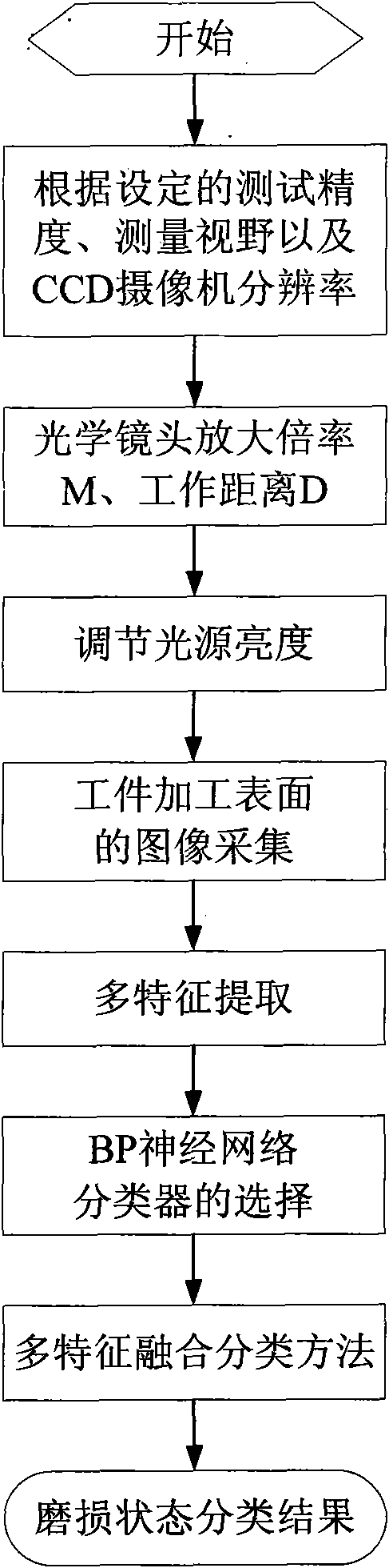
[0024] The technical solution of the present invention will be further described in detail below with examples in conjunction with the accompanying drawings.

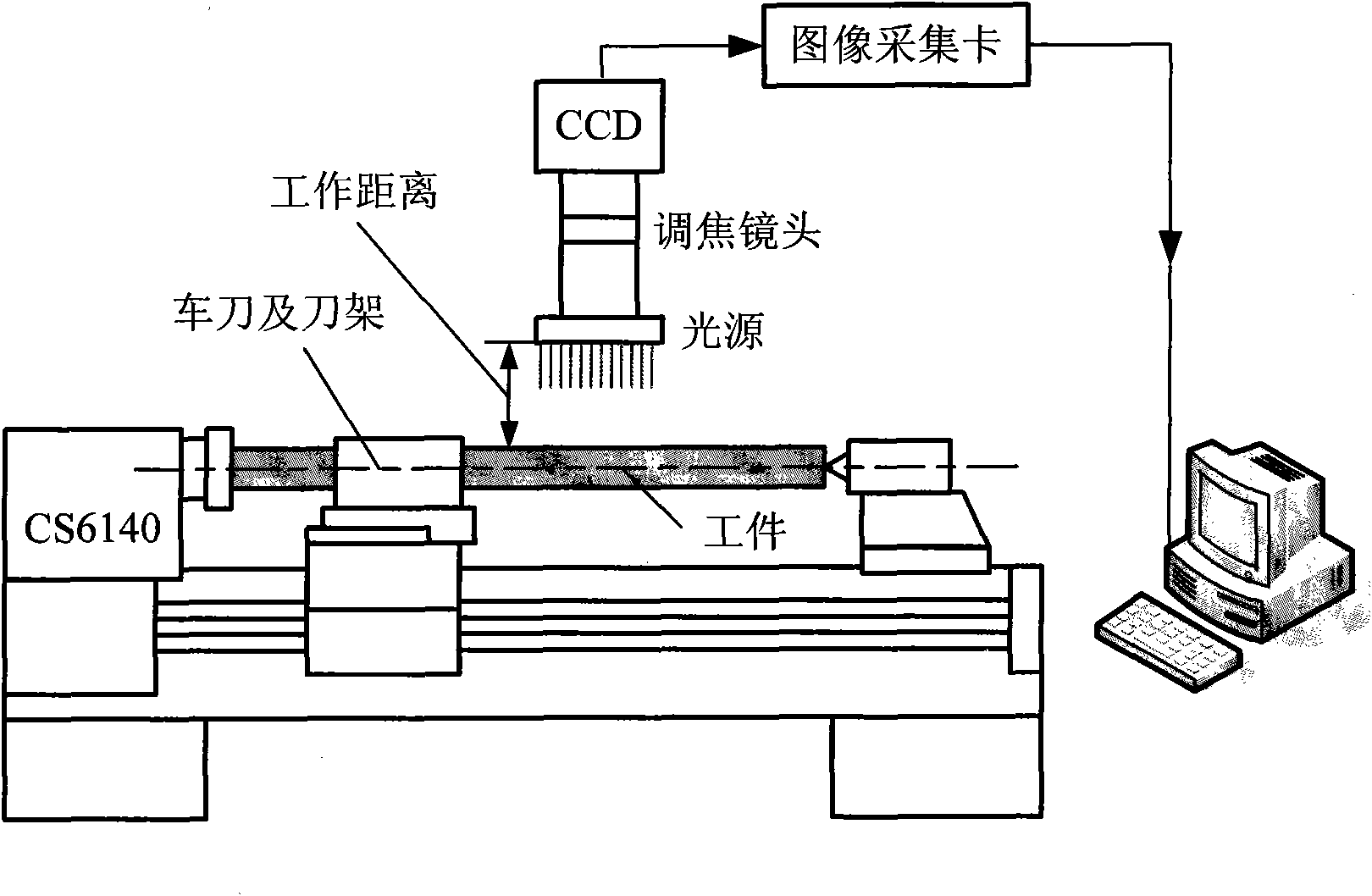
[0025] Such as figure 1 As shown, this embodiment is carried out on a common lathe CS6140, the workpiece to be processed is a shaft with a diameter of Φ180mm, the relevant parameters are 45 steel, quenched and tempered, and the hardness is 225HBW; the cutting tool is a carbide turning tool; round turning. The hardware configuration of the image measurement system is shown in Table 1, and the basic structure diagram is shown in figure 1 As shown, it mainly includes: CS6140 lathe, CCD camera, light source, focusing microscope lens, image acquisition card and computer, etc.

[0026] video camera

COSTAR C400, 1 / 2"Color CCD, pixels 752×582

focus lens

AFT-M0025

frame grabber

Imagenation PCX200Frame Grabber Card

light source

Ose RIN-70-3R-0R

power supply

12V

...


PUM


Abstract

The invention provides a cutting-tool wear state evaluating method based on image analysis of a workpiece machining surface. The method comprises the following steps: firstly acquiring a texture imageof the workpiece machining surface by utilizing optical system imaging; then carrying out multi-feature extractions on the machining surface image and forming a BP neural network classifier facing the machining surface image according to the number of the multi-feature extractions; and adopting a fusion method based on a voting system to fuse the multi-feature classifier so as to realize the qualitative and the quantitative identification of cutting-tool wear and breakage states. The invention can better overcome the defect that the on-line image acquisition of cutting points of a cutting-tool cannot be carried out in a cutting machining process, accurately identify the wear and breakage states of the cutting-tool and can be applied to the cutting-tool on-line monitoring of numeral control machining tools.

Description

technical field [0001] The invention relates to a detection method based on image recognition, in particular to a tool wear state evaluation method based on workpiece processing surface image analysis, which is used in the technical field of electronic measurement. Background technique [0002] Tool wear is an unavoidable phenomenon in the cutting process. Once the tool is worn or damaged, it will not only reduce the machining accuracy of the workpiece, increase the surface roughness, but also increase the cutting force, increase the cutting temperature, and even cause vibration. Interrupt normal cutting process. In the cutting process, tool wear is a gradual process, and the change is relatively slow. The operator can estimate the wear degree of the tool according to the vibration and noise during the cutting process, and consider whether to change the tool or sharpen it. However, due to the randomness of the tool life, this subjective evaluation method is often too conse...

Claims


Application Information

Patent Timeline
IPC IPC(8): B23Q17/24G06K9/62
Inventor 张永宏
Owner NANJING UNIV OF INFORMATION SCI & TECH
Why Eureka
Try Eureka