
Track for high-temperature super-conductivity magnetic levitation transport system

A transportation system and high-temperature superconducting technology, which is applied in transportation and packaging, electric traction, electric vehicles, etc., can solve the problems of inner magnetic field strength enhancement, waste, and cost increase, so as to achieve stable and reliable operation and avoid eccentricity Effect

Inactive Publication Date: 2010-03-17
SOUTHWEST JIAOTONG UNIV
View PDF0 Cites 3 Cited by
  • Summary
  • Abstract
  • Description
  • Claims
  • Application Information

AI Technical Summary

Problems solved by technology

[0006] However, when the existing high-temperature superconducting maglev transportation system passes a curve, the vehicle body is always subjected to the centrifugal force directed to the outside of the curve, so that the vehicle body always produces a large deviation to the outside when the curve is turned, and deviates from the reference point. If the speed of the vehicle is too high or the curve is too sharp or other accidental factors also produce the effect of lateral deviation, the restoring force of the magnetic levitation track will not be enough to offset the lateral deviation, resulting in serious accidents such as derailment
[0007] The outer deviation of the car body at the curve will continue to the next straight line. If the magnetic field strength is not enough, it will not be able to return to the baseline and run, which will also make the maglev transportation system prone to eccentricity and derailment.
[0008] If the overall magnetic field strength of the track is increased, although it can ensure that the train does not deviate from the outer side of the curve with a large amount of deviation, the inner magnetic field strength is also greatly increased, resulting in waste and increased costs.

Method used


Image

  • Track for high-temperature super-conductivity magnetic levitation transport system
  • Track for high-temperature super-conductivity magnetic levitation transport system
  • Track for high-temperature super-conductivity magnetic levitation transport system

Examples


Embodiment 1

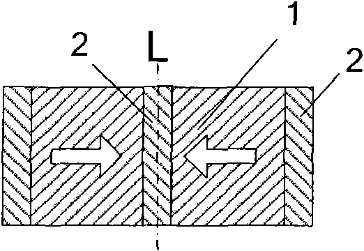
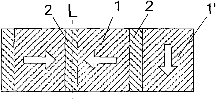
[0033] Figure 1a , 1b , 2a, 2b and Figure 7 It is shown that a specific embodiment of the present invention is: a high-temperature superconducting maglev transportation system track, the track is symmetrically distributed with permanent magnets 1 and magnetic poles 2 on both sides of the reference line L, and the curved part of the track is on the reference line L A row of auxiliary permanent magnets 1' is added laterally on the outside of the

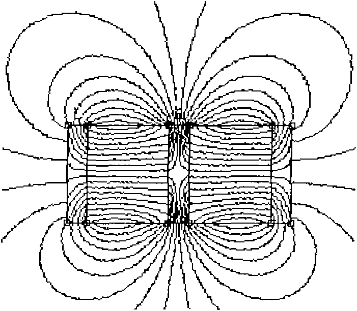
[0034] Figure 1a It can be seen that the straight part of this example has the same structure as a translational symmetric magnetic levitation track currently used, and its permanent magnets are symmetrically distributed on both sides of the reference line L of the track. Figure 1b It can be seen that the magnetic field distribution in the straight part of the track is symmetrically distributed on both sides of the reference line.

[0035] Figure 1a with Figure 2a It is also shown that the magnetization direction of each colum...

Embodiment 2

[0039] Figure 1a , 1b , 3a, 3b show that this embodiment is basically the same as Embodiment 1, the only difference is that two rows of auxiliary permanent magnets 1' are added laterally outside the reference line in the curved part of the track, and the added auxiliary permanent magnets 1' are In the third and fourth columns, the magnetization directions are downward and to the right in turn.

[0040] from Figure 3bIt can be seen that after adding two columns of auxiliary permanent magnets 1' in this example, the horizontal strong magnetic field area outside the reference line L is expanded, so that the magnetic field is asymmetrically distributed to the reference line L. Compared with the inner (left) side, the area outside the reference line L The magnetic field increases on the (right) side. and, from Figure 3b It can also be seen that a magnetic potential well composed of three magnetic force line convex peaks is formed above the track in this example, and the two s...

Embodiment 3

[0043] Figure 4a , 4b , 5a, and 5b show that the third specific embodiment of the present invention is: a high-temperature superconducting maglev transportation system track, and the track has permanent magnets 1 and magnetic gathering poles 2 symmetrically distributed on both sides of the reference line L. A row of auxiliary permanent magnets 1' is added laterally on the outside of the reference line in the curved part of the track.

[0044] In this example, the magnetization direction of each column of permanent magnets is: from the inner (left) side, the first column is right, the second column is upward, the third column is left, and the fourth column is the auxiliary permanent magnet 1 ' added at the bend. Its direction is downward.

[0045] Figure 4a It can be seen that the permanent magnets in the straight part of this example are symmetrically distributed on both sides of the reference line L of the track. Figure 4b It can be seen that the magnetic field distrib...


PUM


Abstract

The invention relates to a track for a high-temperature super-conductivity magnetic levitation transport system. The track is symmetrically distributed with a permanent magnet (1) and a poly-magneticpole (2) at two sides of a datum line (L); the bend part of the track is transversely added with 1-5 columns of auxiliary permanent magnets (1') at the outer side of the datum line (L); when the magnetic levitation transport system makes a turn, the track can produce an enough guide restoring force directing towards the inner side for the magnetic levitation transport system so as to prevent the magnetic levitation transport system from being eccentric and escaping from the track and to guarantee the safe and reliable operation of the magnetic levitation transport system; besides, the track for a high-temperature super-conductivity magnetic levitation transport system has less investment and low cost. Compared with the existing translational symmetric track, the track for a high-temperature super-conductivity magnetic levitation transport system has good compatibility and provides convenience to the reconstruction and upgrading of the existing track.

Description

technical field [0001] The invention relates to a high-temperature superconducting magnetic suspension transportation system, in particular to a track of the high-temperature superconducting magnetic suspension transportation system. Background technique [0002] Commonly used high-temperature superconducting materials are rare earth REBaCuO superconducting bulk materials such as yttrium barium copper oxide superconductor (YBaCuO) or gadolinium oxide superconductor (GdBaCuO). The unique magnetic flux pinning ability of these superconducting bulk materials in the superconducting mixed state is used to achieve self-stabilization, no input energy, and a suspension state in a continuous stable interval. This unique and novel self-stabilizing suspension system has relatively simple realization conditions and is very suitable for large-scale engineering applications. Therefore, more than 20 years since the discovery of high-temperature superconducting materials, experimental demo...

Claims


Application Information

Patent Timeline
IPC IPC(8): B60L13/04
Inventor 郑珺邓自刚林群煦刘伟叶常青王家素王素玉
Owner SOUTHWEST JIAOTONG UNIV
Learn More