Electric equipment control device and method

A technology of electrical equipment and control devices, which is applied in the direction of circuit devices, electrical components, etc., can solve problems such as hidden dangers of power consumption and inconvenience for users, and achieve the effect of reducing hidden dangers of power consumption

Inactive Publication Date: 2010-03-17
STATE GRID CORP OF CHINA +1
View PDF0 Cites 27 Cited by
  • Summary
  • Abstract
  • Description
  • Claims
  • Application Information

AI Technical Summary

Problems solved by technology

Usually, when we shut down the electrical equipment, we actually put the electrical equipment in the standby state. In the standby state, the electrical equipment does not completely stop working, there is still a small amount of power consumption, and there is still a certain Potential safety hazards in electricity use. Only by disconnecting the power supply of the electrical equipment can the electrical equipment be completely shut down.
However, using the existing intelligent control method of electrical equipment, there are also the above problems: the user still needs to manually disconnect the power of the electrical equipment to completely shut down the electrical equipment; and, when the electrical equipment is completely turned off, only When the user manually connects the electrical equipment to the power supply, the control terminal can work again, causing inconvenience to the user

Method used


Image

  • Electric equipment control device and method
  • Electric equipment control device and method
  • Electric equipment control device and method

Examples


Embodiment Construction

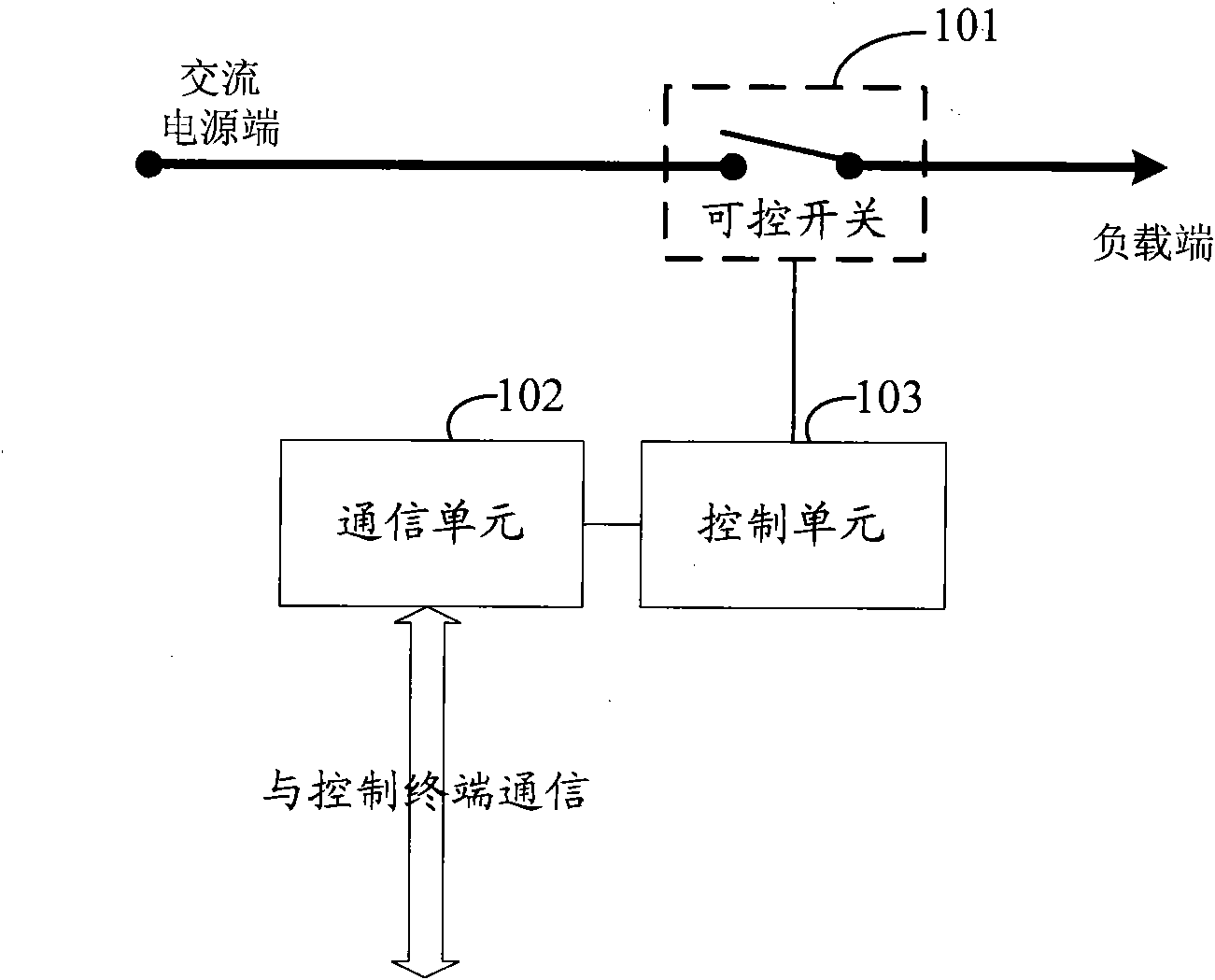
[0021] Firstly, an electric equipment control device of this application will be described. For a schematic diagram of the internal structure of the device, please refer to figure 1 As shown, it includes: a controllable switch 101, a communication unit 102, and a control unit 103;

[0022] Among them, the controllable switch 101 is connected in series between the AC power end and the load end of the power supply path of the electrical equipment; when the controllable switch 101 is opened or closed, the AC power supply path is in an open or conducting state, respectively.

[0023] The opening or closing of the controllable switch 101 is controlled by the control unit 103. In this embodiment, the electrical equipment is connected to the load end of the power supply path. When the user needs to control the complete closing and opening of the electrical equipment, the control can be used directly The terminal performs remote operation. The control terminal generates a control message ac...


PUM


Abstract

The request discloses an electric equipment control device and a method. The device comprises a controllable switch, a communication unit and a control unit. The controllable switch is connected between the alternating current power supply end and the load end of a power supply path of the electric equipment. The communication unit is used for receiving the control signal sent by a user control terminal. The control unit is used for connecting or disconnecting the controllable switch according to the control signal received by the communication unit. By applying the above technical scheme, theuser can directly use the control terminal to control the power supply of the electric equipment and realize complete closing and opening of the electric equipment by disconnecting or connecting theelectric equipment and the power supply. Compared with the prior art, by applying the technical scheme provided by the request, optimum control of the power dissipation of the electric equipment can be realized and potential electric safety hazards of the electric equipment can be reduced on the premise of not needing the user to plug and unplug the power supply of the electric equipment manually.

Description

Technical field [0001] This application relates to the field of smart home technology, and in particular to a device and method for controlling electrical equipment. Background technique [0002] With the continuous progress of technology and society, smart homes have gradually approached ordinary users. Smart home is the use of computer, network communication and other technologies to organically combine various subsystems related to home life. Smart home can provide a full range of information exchange functions, thereby providing users with more comfort, convenience and safety. Living environment. [0003] The intelligent control of household electrical equipment is an important aspect of realizing smart home. The existing intelligent control method of electric equipment is realized through an intelligent control terminal, and the corresponding receiving module is required to be installed on the electric equipment. The control terminal and the receiving module installed on th...

Claims


Application Information

Patent Timeline
Patent Type & Authority Applications(China)
IPC IPC(8): H02J13/00
Inventor 刘建明赵丙镇黄长贵陈建峰栗宁
Owner STATE GRID CORP OF CHINA
Why Eureka
Try Eureka