Sampling hold circuit applied to analogue-to-digital converter

A sample-and-hold circuit and analog-to-digital converter technology, applied in the direction of analog/digital conversion, code conversion, electrical analog memory, etc., can solve the problems affecting the accuracy and gain error of the sample-and-hold circuit

Inactive Publication Date: 2010-03-17
INST OF SEMICONDUCTORS - CHINESE ACAD OF SCI
View PDF0 Cites 11 Cited by
  • Summary
  • Abstract
  • Description
  • Claims
  • Application Information

AI Technical Summary

Problems solved by technology

On the one hand, the op amp is not an ideal op amp, and there is a gain error; on the other hand, since the sample-and-hold circuit is a switched capacitor circuit, its o

Method used


Image

  • Sampling hold circuit applied to analogue-to-digital converter
  • Sampling hold circuit applied to analogue-to-digital converter
  • Sampling hold circuit applied to analogue-to-digital converter

Examples


Embodiment Construction

[0027] In order to make the object, technical solution and advantages of the present invention clearer, the present invention will be described in further detail below in conjunction with specific embodiments and with reference to the accompanying drawings.

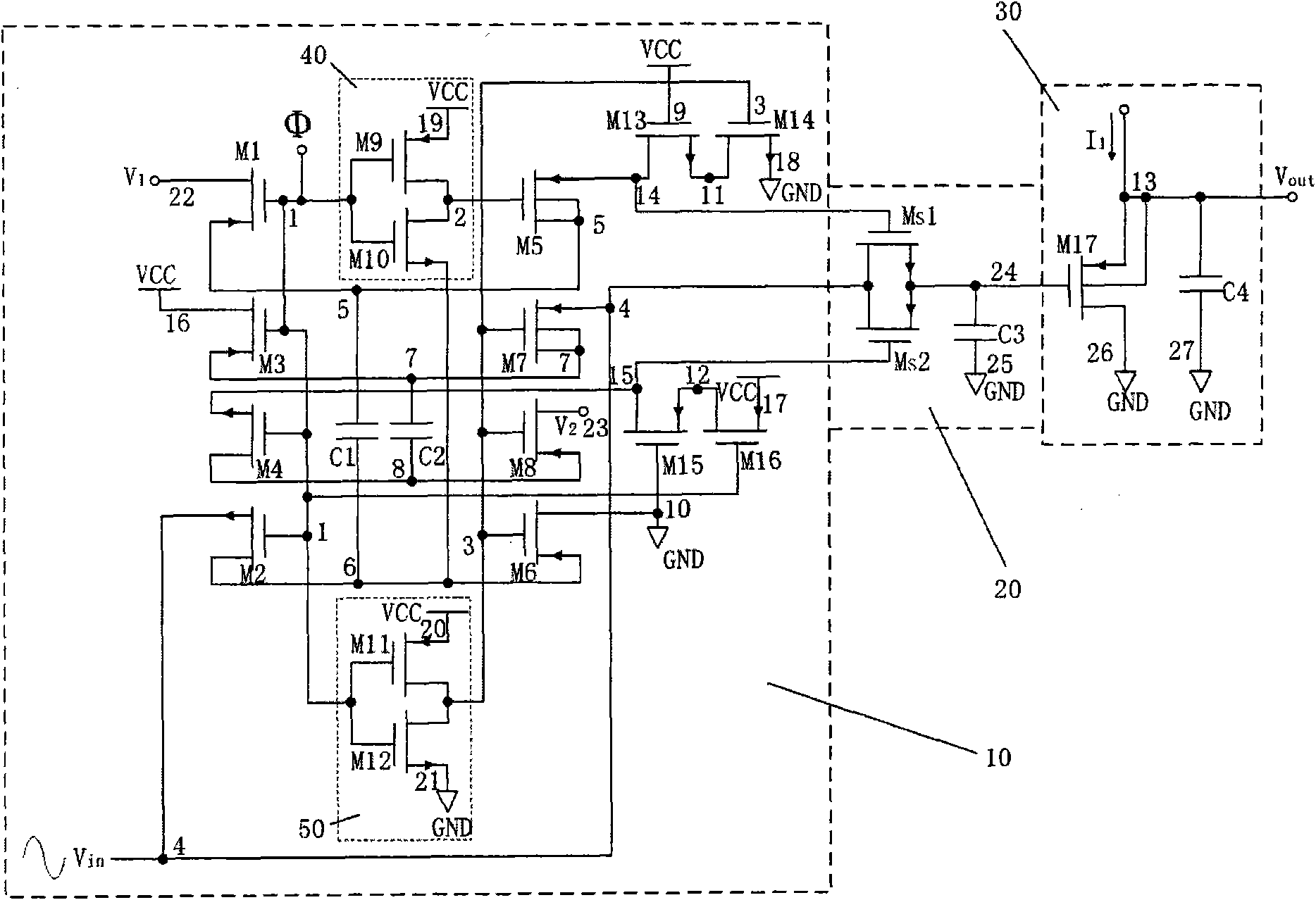
[0028] Such as image 3 and Figure 4 As shown, the sample-and-hold circuit applied to an analog-to-digital converter provided by the present invention includes a sampling switch bootstrap circuit 10 , a sampling network 20 and a source follower 30 . The output end of this sampling switch bootstrap circuit 10 is connected with the input end of sampling network 20, and the output end of this sampling network 20 is connected with the input end of source follower 30, and the 13th node 13 of source follower 30 is this sample hold circuit The output Vout.

[0029]In the sampling switch bootstrap circuit 10, the fourth node 4 as an input terminal is connected to the sinusoidal input signal Vin, the 22nd node 22 is connected t...


PUM


Abstract

The invention discloses a sampling hold circuit applied to an analogue-to-digital converter, which comprises a sampling switch bootstrap circuit (10), a sampling network (20) and a source follower (30). The output end of the sampling switch bootstrap circuit (10) is connected with the input end of the sampling network (20); the output end of the sampling network (20) is connected with the input end of the source follower (30); and a thirteenth node (13) of the source follower (30) is the output Vout of the sampling hold circuit. Compared with the conventional sampling hold circuit, the sampling hold circuit applied to the analogue-to-digital converter eliminates the nonlinearity of a switch conducting resistance, reduces signal distortion and improves the accuracy of the circuit due to theadoption of the bootstrap circuit.

Description

technical field [0001] The invention relates to the technical field of sample and hold (Track and Hold) circuits, in particular to a sample and hold (Track and Hold) circuit including a bootstrap circuit applied to an analog-to-digital converter. Background technique [0002] A sample-and-hold circuit (sample / hold) is also called a sample-and-hold amplifier. General sample and hold circuits are implemented using switched capacitor circuits. A switched capacitor circuit is a circuit consisting of switches and capacitors controlled by a clock signal. It uses the storage and transfer of charges to realize various processing functions of signals. In actual circuits, sometimes circuits composed of only switches and capacitors often do not meet the requirements, so they are often combined with amplifiers or operational amplifiers, comparators, etc. to realize the generation, conversion and processing of electrical signals. [0003] figure 1 for a basic switched capacitor ampli...

Claims


Application Information

Patent Timeline
IPC IPC(8): H03M1/34G11C27/02
Inventor 张强倪卫宁石寅
Owner INST OF SEMICONDUCTORS - CHINESE ACAD OF SCI
Why Eureka
Try Eureka