Production process of electroacoustic component

An electro-acoustic element and production process technology, applied in the field of electronics, can solve the problems of inability to adapt to the development trend of miniaturization of microphones, complex structure of electro-acoustic elements, difficult to automate production, etc., and achieve simple structure, good conductive effect, and production cost. low effect

Inactive Publication Date: 2010-03-17
WEIFANG ANJING ELECTRONICS
View PDF0 Cites 2 Cited by
  • Summary
  • Abstract
  • Description
  • Claims
  • Application Information

AI Technical Summary

Problems solved by technology

[0013] Due to the complex structure of this electro-acoustic element, the traditional production process is relatively cumbersome, and most of them are manually operated, so it is difficult to realize automatic production, so the production efficiency is low and the production cost is high. For miniature and ultra-thin electro-acoustic elements Said that it is more difficult to assemble, the yield of the product is very low, and it can no longer adapt to the trend of miniaturization of the microphone

Method used


Image

  • Production process of electroacoustic component
  • Production process of electroacoustic component
  • Production process of electroacoustic component

Examples


Embodiment 1

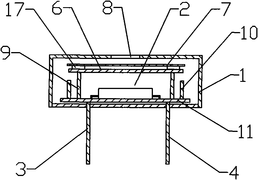
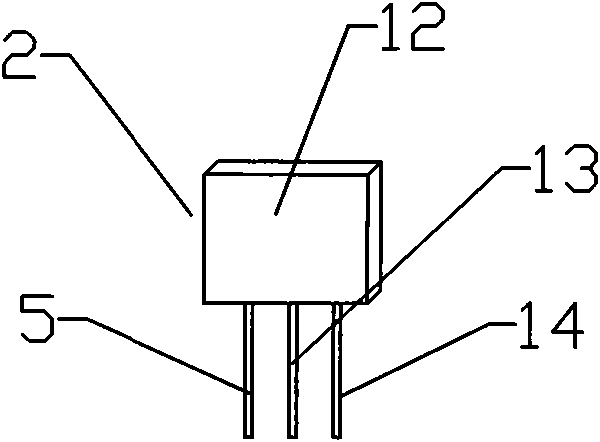
[0044] Embodiment 1, with Figure 4 Schematic diagram of the structure of the electro-acoustic components, attached Figure 5 It is a schematic diagram of the structure of a field effect transistor. The electroacoustic element includes a metal shell 1 with a sound transmission hole 8 on the top, a field effect tube 2 , a pole plate 6 , a vibrating membrane 7 , a first lead pin 3 , a second lead pin 4 and an isolation ring 17 .

[0045] The production process of the above electro-acoustic components includes the following steps:

[0046] 1) Make FET 2:

[0047] The field effect tube 2 is processed into a field effect tube body 12 with an upper surface and a lower surface, a grid 5 carrying an end face is processed on the upper surface of the field effect tube body 12, and a drain is processed on the lower surface of the field effect tube body 12. pole 13 and source 14;

[0048] 2) Assembling the pole plate 6 on the bearing end face of the grid 5;

[0049] 3) Conductive glu...

Embodiment 2

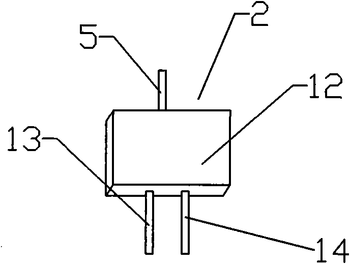
[0053] Embodiment 2, with Image 6 Schematic diagram of the structure of the electro-acoustic components, attached Figure 7 It is a schematic diagram of the structure of a field effect transistor. The electroacoustic element includes a metal shell 1 with a sound transmission hole 8 on the top, a field effect tube 2 , a pole plate 6 , a vibrating membrane 7 , a first lead pin 3 , a second lead pin 4 and an isolation ring 17 .

[0054] The production process of the above electro-acoustic components includes the following steps:

[0055] 1) Make FET 2:

[0056]The field effect tube body 12 is processed into a structure in which the middle is a disc, and its upper surface and lower surface are circular truncated structures. The upper bottom surface 16 of the upper surface circular platform forms the upper surface of the field effect tube body 12. position and process a cylindrical grid 5 with a bearing end face, the lower bottom surface 15 of the lower surface circular platfor...


PUM


Abstract

The invention relates to a production process of an electroacoustic component which comprises a shell, a field effect transistor, a polar plate, a vibrating diaphragm, a first terminal pin, a second terminal pin and a spacing ring, wherein a sound conducting hole is arranged at the upper part of the shell. The production process comprises the following steps: manufacturing the field effect transistor, assembling the polar plate, arranging conductive adhesive, assembling the spacing ring, installing the vibrating diaphragm and finally packaging. A drain electrode of the field effect transistorforms the first terminal pin of the electroacoustic component, a source electrode forms the second terminal pin of the electroacoustic component, the polar plate is assembled on a bearing end surfaceof the grid electrode, the bearing end surface of the grid electrode performs the function of supporting the polar plate, and the drain electrode and the source electrode can directly form the terminal pins of the electroacoustic component, thereby saving the steps in a traditional processing method, decreasing components and parts, simplifying the structure, lowering the cost, additionally decreasing the processing working procedures, improving the processing efficiency and easily realizing automatic production.

Description

technical field [0001] The invention relates to a production process of electronic components, in particular to a production process of electroacoustic components, belonging to the field of electronic technology. Background technique [0002] In the electroacoustic industry, electroacoustic components are generally used as sound transmission devices. The electroacoustic components currently used generally have a structure such as figure 1 As shown, a metal shell 1 is included, and the shell 1 has a sound transmission hole 8, a first lead pin 3 and a second lead pin 4, and a field effect tube 2 for converting a sound signal into a current signal is arranged in the shell 1, The field effect tube 2 is installed on the circuit board 11, and the vibrating membrane 7, the isolation ring 17 and the pole plate 6 are arranged successively between the sound transmission hole 8 and the field effect tube 2, and the commonly used field effect tube 2 is as follows figure 2 and as imag...

Claims


Application Information

Patent Timeline
Patent Type & Authority Applications(China)
IPC IPC(8): H04R31/00H04R1/04H01L21/336H01L29/78
Inventor 潘难德
Owner WEIFANG ANJING ELECTRONICS
Why Eureka
Try Eureka