
Valve and processing device with the valve

An exhaust device and valve body technology, applied in valve devices, sliding valves, valve details, etc., can solve the problems of decreased processing capacity, high cost of sealing components, increased manufacturing cost and maintenance cost of gate valves, etc., and achieves reduction of maintenance costs. , low cost, low manufacturing effect

Inactive Publication Date: 2010-03-17
TOKYO ELECTRON LTD
View PDF3 Cites 18 Cited by
  • Summary
  • Abstract
  • Description
  • Claims
  • Application Information

AI Technical Summary

Problems solved by technology

[0011] At present, as the energy of plasma and free radicals increases, in order to improve the resistance to plasma and free radicals, relatively expensive sealing parts made of completely fluorinated rubber are used, but deterioration is still unavoidable. The sealing parts must be replaced in a few months, and the cost of the sealing parts becomes high
In addition, in order to replace the sealing parts, the device must be in the maintenance state, so the processing capacity is reduced
[0012] In addition, although there are gate valves configured to block the sealing member from plasma and radicals, this gate valve has a structure in which the flow control part (control valve body) and the main valve part (sealing valve body) are integrally formed. Lead to an increase in the manufacturing cost and maintenance cost of the gate valve

Method used


Image

  • Valve and processing device with the valve
  • Valve and processing device with the valve
  • Valve and processing device with the valve

Examples


no. 1 approach

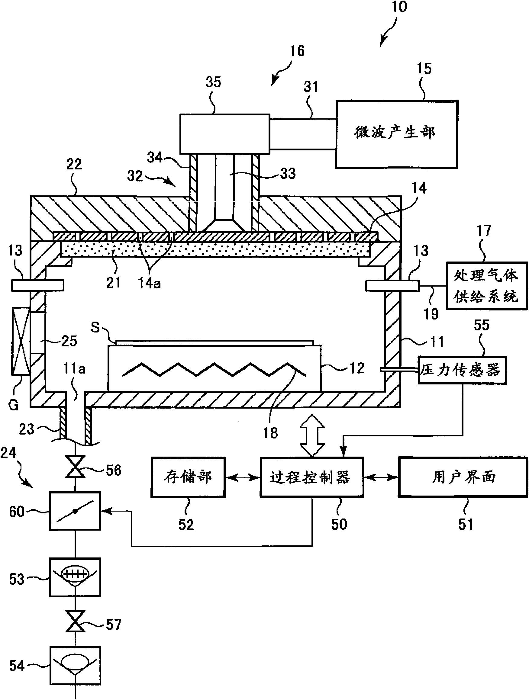
[0076] figure 1 It is a schematic cross-sectional view of an RLSA microwave plasma processing apparatus using the pressure control valve according to the first embodiment of the present invention.

[0077] Such as figure 1 As shown, the RLSA microwave plasma processing device 10 has: a substantially cylindrical cavity 11 for accommodating a semiconductor substrate and maintaining a vacuum; The side wall of 11 is used to introduce the gas introduction part 13 that forms the annular shape of processing gas; It is arranged facing the opening of the upper part of cavity 11, and is formed with the planar antenna 14 of a plurality of microwave penetration holes 14a; The microwave that produces microwave the microwave generating unit 15 ; the microwave transmission mechanism 16 guiding the microwave generating unit 15 to the planar antenna 14 ; and the processing gas supply system 17 supplying the processing gas to the gas introducing unit 13 .

[0078] Below the planar antenna 14,...

no. 2 approach

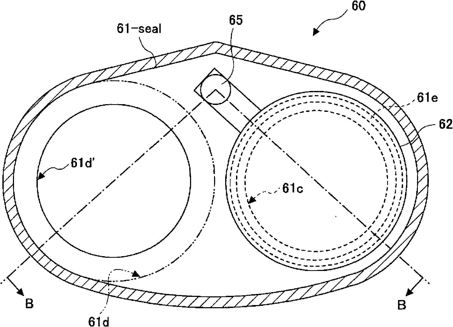
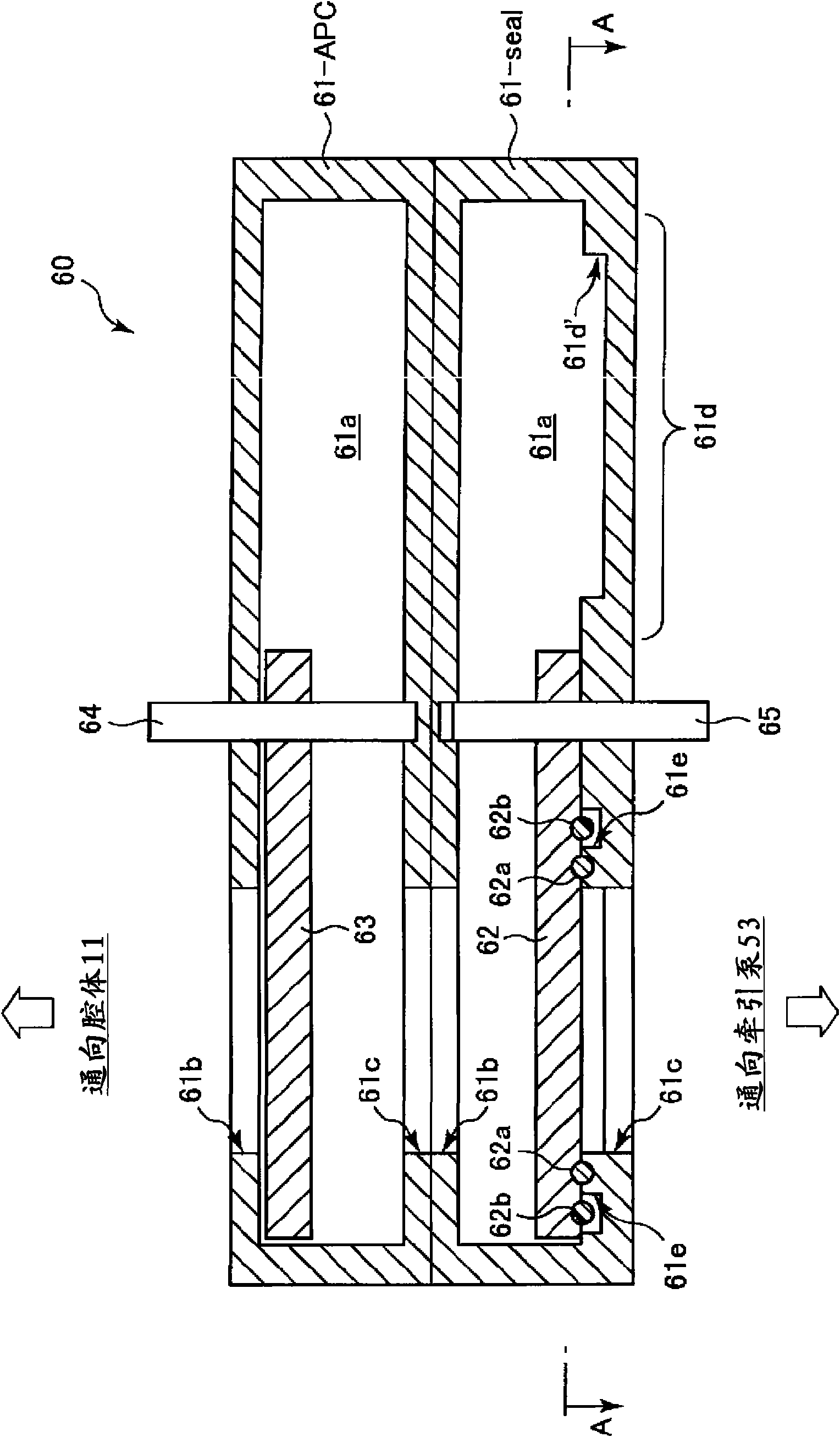
[0112] Figure 7 It is a sectional view showing the structure of the pressure control valve 60 of the second embodiment. Figure 7 The cross-section shown, for example, is the same as that showing the state where the opening is closed by the closing valve body. figure 2 corresponding to the B-B profile.

[0113] Such as Figure 7 As shown, the difference between the second embodiment and the first embodiment is that the rotation shaft 64 and the rotation shaft 65 are coaxial.

[0114] In the pressure control valve 60 of the second embodiment, the part for controlling the pressure is also of the pendulum type like the part for closing. The control valve body 63 is attached to the rotation shaft 64, and rotates around the central axis of the rotation shaft 64 between the opening 61b of the valve main body 61-APC and the space 61a.

[0115] The closing valve body 62 is attached to the rotation shaft 65 . The rotating shaft 65 is formed as a hollow shaft having a hollow port...

Embodiment approach 1

[0118] At this time, even when the rotating shaft 64 and the rotating shaft 65 are coaxial during periodic inspection, inspection and repair can be performed only by removing the valve main body 61-APC or the valve main body 61-seal. Therefore, as in the first embodiment, maintenance of the processing apparatus can be simplified and maintenance costs can be reduced.


PUM


Abstract

A valve provided between a chamber, the pressure inside which can be kept reduced, and an exhaust device for exhausting the inside of the chamber. The valve has a first valve body including a first opening and a second opening that permit flow of gas between the chamber and the exhaust device, a sealing valve body placed in the first valve body and opening and closing the second opening of the first valve body by coming into contact with and separating from the second opening, a seal member provided at the sealing valve body and sealing the second opening of the first valve body when the sealing valve body closes the second opening, a valve shelter section provided at the first valve body at its inner wall section away from the second opening and shielding the seal member from the inner space of the first valve body when the sealing valve body separates and moves from the second opening, and a first pivot shaft for pivoting the sealing valve body and positioning it to either of the second opening of the first valve body and the valve shelter section.

Description

technical field [0001] The present invention relates to a valve provided between a chamber and an exhaust device of a processing device for vacuum processing a target object such as a semiconductor wafer, and a processing device having the valve. Specifically, the present invention relates to a closing valve capable of closing between a cavity of a processing device and an exhaust device, a closing valve having the function of controlling pressure in the cavity, and a processing device having the closing valve. Background technique [0002] In the semiconductor manufacturing process, various vacuum processes such as film formation process and etching process are performed. In the processing device for this vacuum treatment, the semiconductor wafer as the object to be processed is sent into a cavity that can be evacuated inside, and the cavity is evacuated by an exhaust device including a vacuum pump, and the semiconductor wafer is simultaneously evacuated. prescribed proces...

Claims


Application Information

Patent Timeline
Patent Type & Authority Applications(China)
IPC IPC(8): F16K3/18F16K3/00F16K3/02F16K3/04F16K27/04F16K51/02
CPCF16K3/06F16K3/00F16K3/18F16K27/04F16K51/02
Inventor 野沢俊久
Owner TOKYO ELECTRON LTD
Learn More