Steel plate with high strength and low yield ratio

A low-yield ratio, high-strength technology, applied in the field of iron and steel materials, can solve the problems of complex chemical composition, low strength, and increased raw material costs, and achieve the effect of simple production process, low cost, and reduced production costs

Active Publication Date: 2010-03-24
BAOSHAN IRON & STEEL CO LTD
0 Cites 29 Cited by

AI-Extracted Technical Summary

Problems solved by technology

[0010] It can be seen from Table 1 and Table 2 that the strength of the existing low-yield ratio steels is very low, and the chemical composition of the steels involved in some patent d...

Abstract

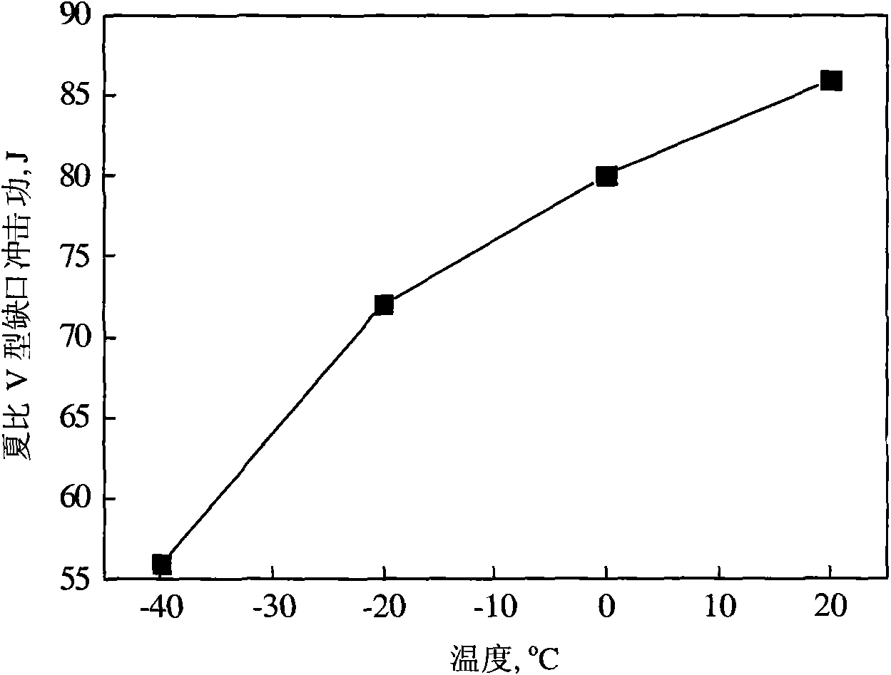
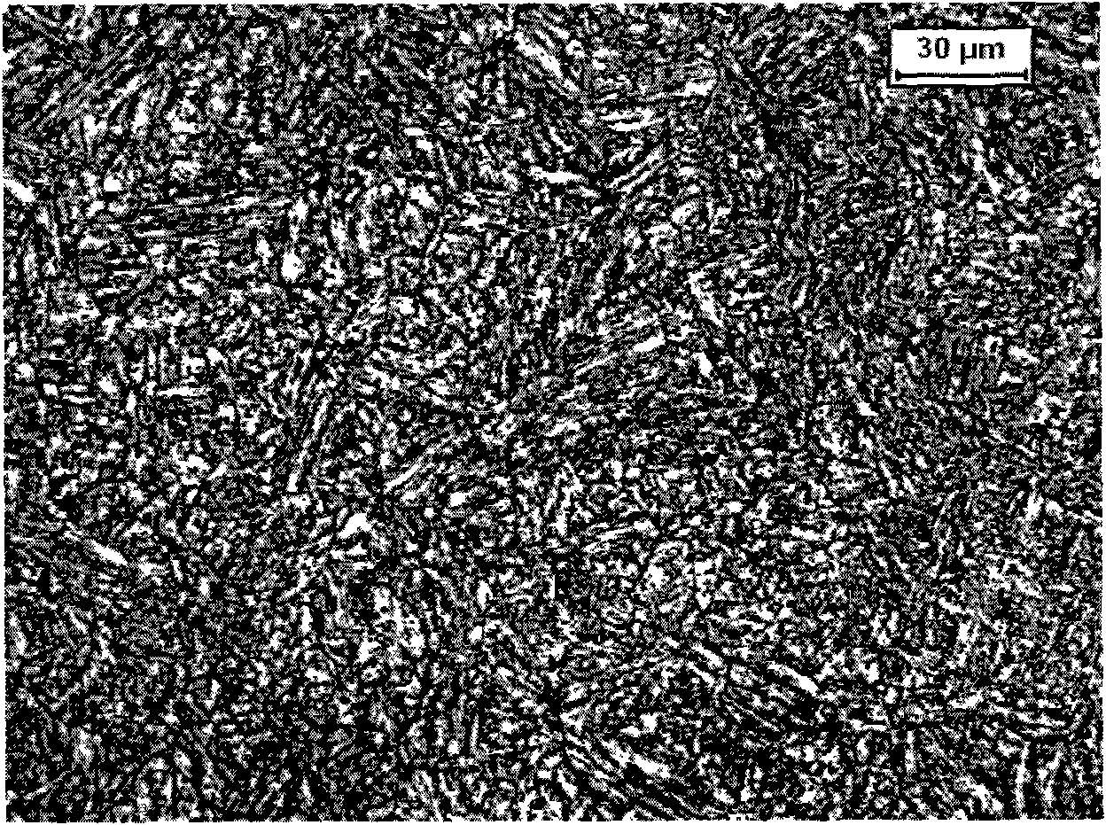
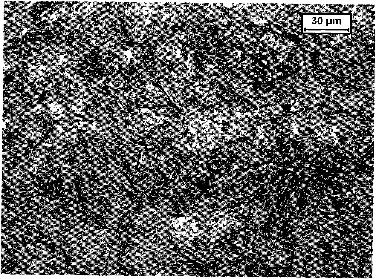
The present invention provides a steel plate with high strength and low yield ratio, which comprises chemical components as follows: C: 0.15-0.20 wt%, Si: 1.0-2.0 wt%, Mn: 1.8-2.0 wt%, Al<=0.036 wt%,V: 0.05-0.1 wt%, P<=0.01 wt%, S<=0.005 wt%, Cr: 0.8-1.0 wt%, the residual is Fe and other unavoidable impurity. The hot-rolling steel plate with high strength and low yield ratio is obtained by adopting low alloyed processing and traditional TMCP rolling technique, which has a strength reaching to 1200-1500 MPa, simultaneously, has better low temperature impact toughness. The steel plate is suitable for the fields requiring high strength and low yield ratio, such as mechanical manufacture, fuel/gas delivery pipeline, building, bridge, steel rail and pressure vessel, etc.

Technology Topic

Steel platesLower yield +5

Image

  • Steel plate with high strength and low yield ratio
  • Steel plate with high strength and low yield ratio
  • Steel plate with high strength and low yield ratio

Examples

  • Experimental program(3)
  • Effect test(1)

Example Embodiment

[0026] Example 1
[0027] According to the chemical composition shown in Table 3, the molten steel is smelted in a converter or an electric furnace, and then secondarily refined in a vacuum furnace, and cast into a billet (ingot) with a thickness of 220 mm. The billet (ingot) is heated to 1200 ° C and kept for 1 to 2 hours. Then rolling, the starting rolling temperature is 1000-1070°C, the rolling thickness is 120-220mm, the cumulative deformation above 950°C is ≥50%, the intermediate billet is heated at about 1000°C to 900°C, and the final rolling temperature is 800- 850°C, the thickness of the steel plate is 100mm, water cooling is carried out at a speed of 8-10°C/s after rolling, and the final cooling temperature is 500-550°C.

Example Embodiment

[0028] Example 2
[0029] Except that the billet (ingot) heating temperature is 1200° C. and the thickness of the steel plate is 40 mm, other implementations are the same as in Example 1.

Example Embodiment

[0030] Example 3-5
[0031] Except that the billet (ingot) heating temperature is 1150° C. and the thickness of the steel plate is 80 mm, other implementations are the same as in Example 1.
[0032] Table 3 Chemical composition (wt %) of the steel plate of embodiment 1-5 of the present invention
[0033]

PUM

no PUM

Description & Claims & Application Information

We can also present the details of the Description, Claims and Application information to help users get a comprehensive understanding of the technical details of the patent, such as background art, summary of invention, brief description of drawings, description of embodiments, and other original content. On the other hand, users can also determine the specific scope of protection of the technology through the list of claims; as well as understand the changes in the life cycle of the technology with the presentation of the patent timeline. Login to view more.

Similar technology patents

Self-venting valve end cap and method

ActiveUS6972092B1Reduce manufacturing costImproves filter reliability and wear characteristicCombination devicesAuxillary pretreatmentEngineeringDiesel engine
Owner:WIX FILTRATION

Classification and recommendation of technical efficacy words

  • Reduce manufacturing cost
  • Simple production process
Why Eureka
Try Eureka