Arrangement and method for blanket gas supply control for an electrical welding apparatus

A technology of shielding gas and electric welding machine, which is used in arc welding equipment, manufacturing tools, welding equipment, etc.

Active Publication Date: 2010-03-24
ALEXANDER BINZEL SCHWEISSTECHN GMBH & CO
View PDF1 Cites 12 Cited by
  • Summary
  • Abstract
  • Description
  • Claims
  • Application Information

AI Technical Summary

Problems solved by technology

[0006] It is an object of the present invention to provide a solution to the above-mentioned and other problems associated with the initial phase of electric welding operations and to improve the welding operation when welding occurs in connection with the initial phase of electric welding operations

Method used


Image

  • Arrangement and method for blanket gas supply control for an electrical welding apparatus
  • Arrangement and method for blanket gas supply control for an electrical welding apparatus
  • Arrangement and method for blanket gas supply control for an electrical welding apparatus

Examples


Embodiment Construction

[0017] In the following, the invention will be explained in more detail by means of advantageous embodiments.

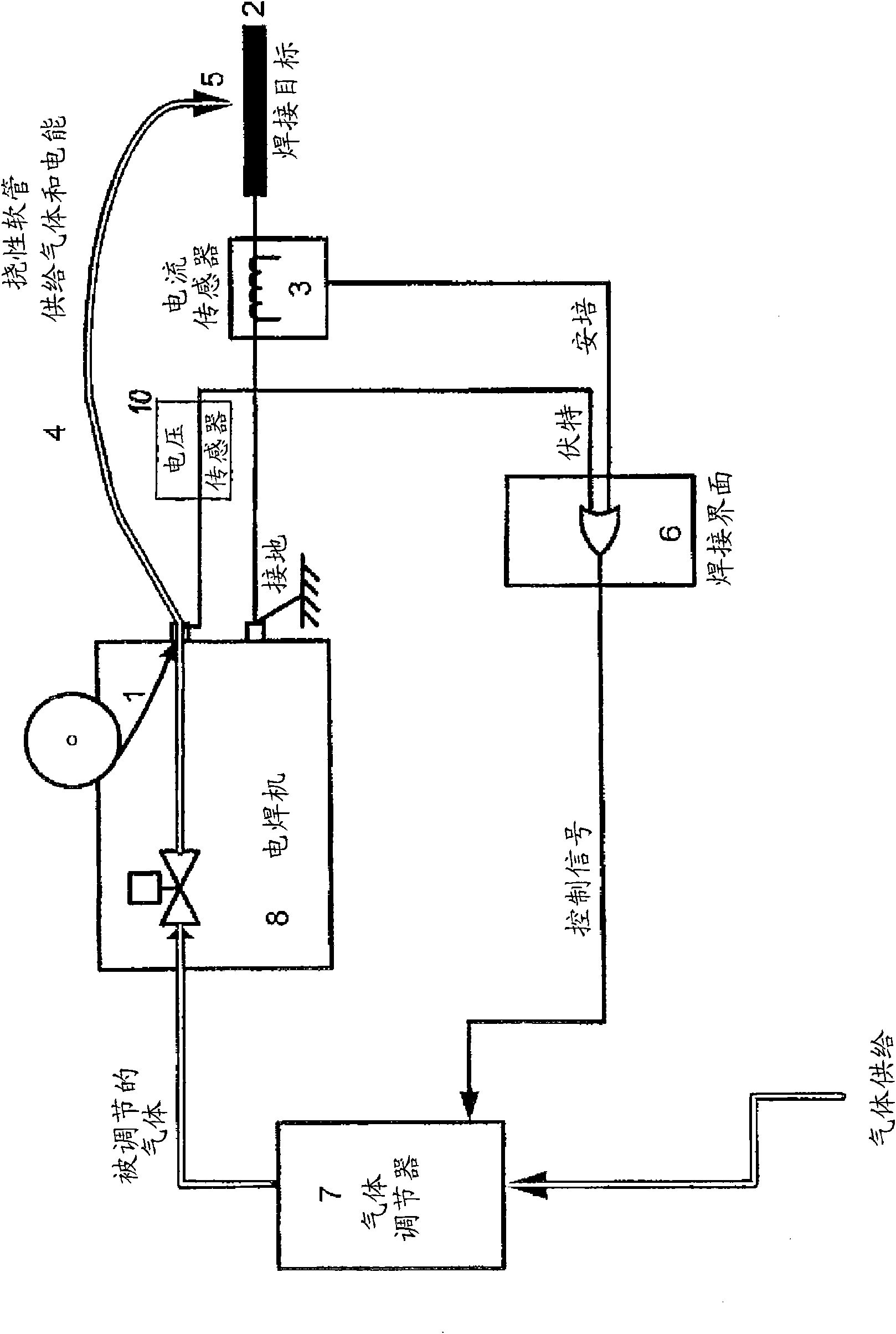
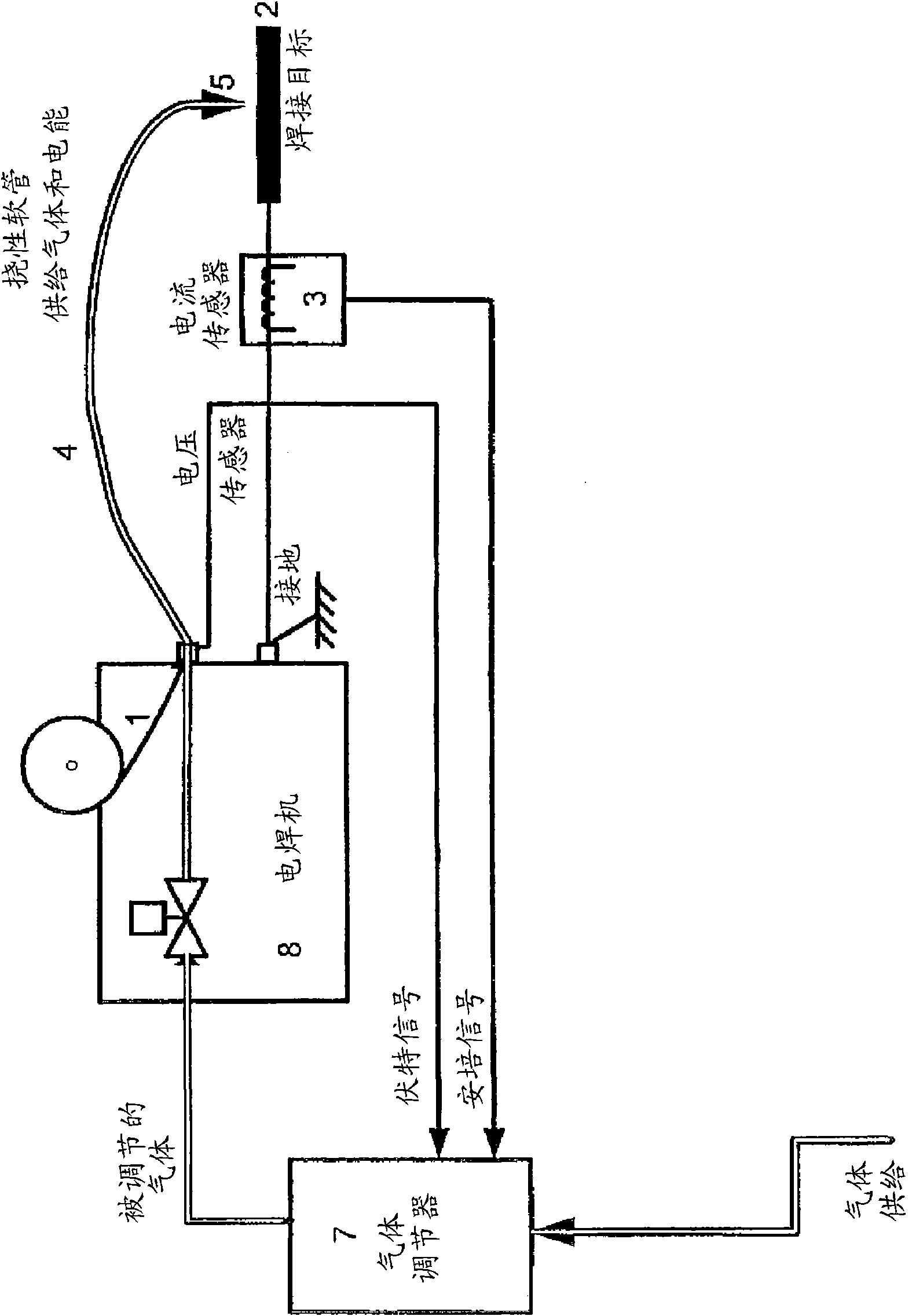
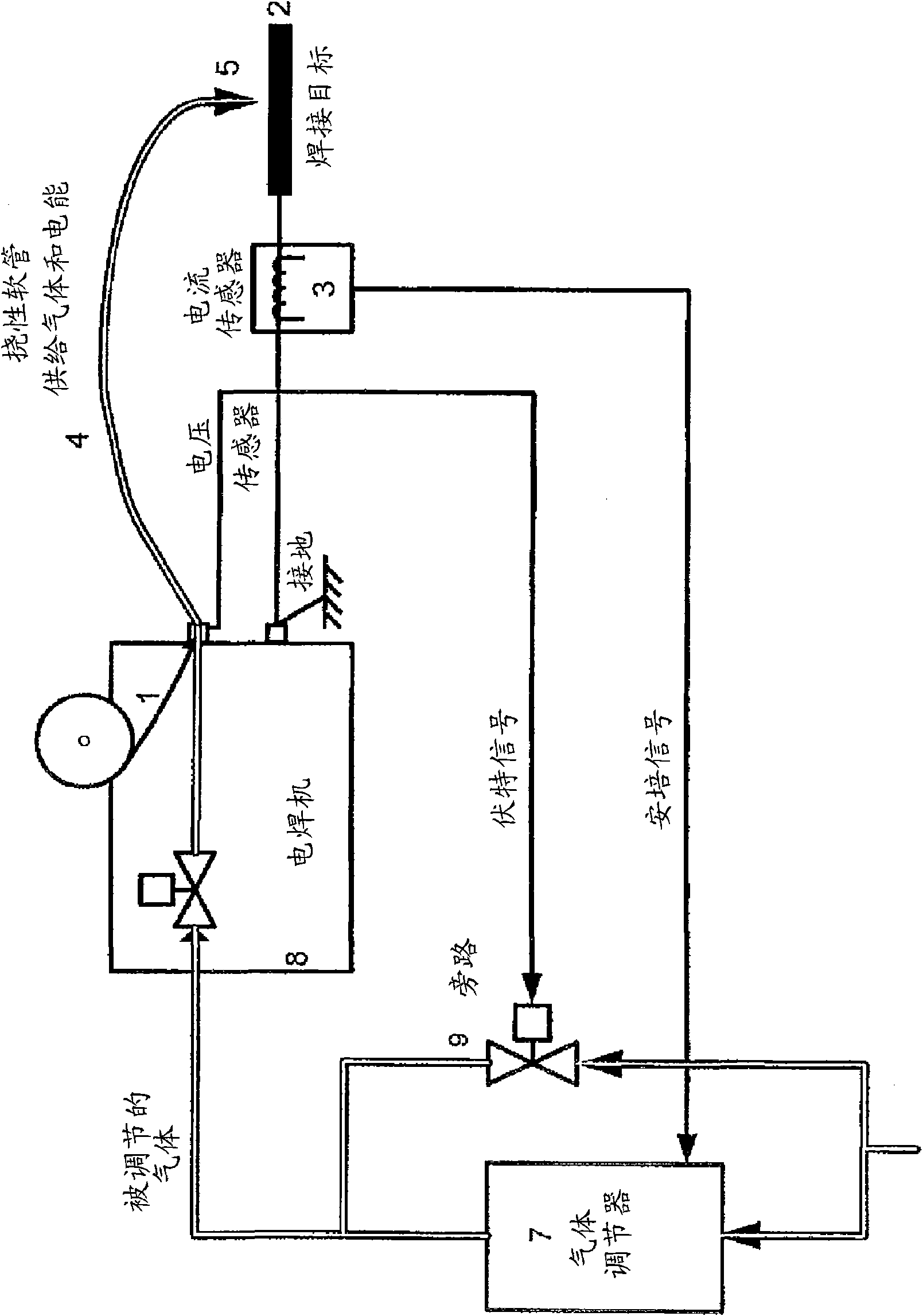
[0018] figure 1 A first embodiment of the invention is shown in which a gas regulator 7 incorporated into the shielding gas supply line of an electric welding machine 8 is adapted to regulate the output flow of shielding gas in response to the Control signal, the control signal comes from a voltage signal and a current signal, the voltage signal is provided by a voltage sensor arranged to detect the voltage supply from the welding machine 8 to the electrode 5, and the current signal (ampere) is arranged to be detected in the welding current path The current sensor 3 of the current supplies, for example, the current in the conducting circuit of the welding machine 8 to the welding power source of the welding rod 5 or, preferably, the current in the power supply connection between the object 2 to be welded and the welding machine 8 . The welding interface 6 receives v...


PUM


Abstract

Apparatus and method for use in controlling blanket gas flow in an electrical welding facility, wherein welding is performed using a welding electrode in electrical connection with a welding machine unit. The apparatus comprises an electric measuring device having a current sensor 3 adapted to determine the magnitude of an electrical welding current carried in a circuit incorporating the welding electrode and having a current sensor output adapted to provide a I signal indicating the current magnitude, and a voltage sensor 11 adapted to determine the magnitude of an electrical voltage being applied to the welding electrode and having a voltage sensor output for providing a U signal indicating the voltage magnitude, and a control device 6. The control device 6 has inputs connected to the current sensor output and the voltage sensor output, respectively, and a control signal output for providing a control signal to a blanket gas flow controller 7, and a controller adapted to provide thecontrol signal as a) a control signal of a predetermined first magnitude when the U signal is larger than the first U threshold and the I signal is less than a first I threshold, and b) a control signal of a magnitude varying proportionally with the I signal when the I signal is greater than the first I threshold.

Description

technical field [0001] The present invention relates to the field of providing shielding gas, also known as shielding gas or reactive gas, to the welded joint in electric welding installations, and in particular the invention relates to a method for controlling shielding gas (shielding gas, reactive gas) at various stages of the welding operation Flow method and apparatus. Background technique [0002] For electric welding operations, the welding joint will be equipped with a blanket of inert shielding gas supplied from a central shielding gas supply or from cylinders located near the welding machine components of the welding equipment. The shielding gas provided by the supply device or the gas cylinder generally has a pressure value which exceeds the pressure of the shielding gas which can be controlled by the shielding gas control device of the welding device. In order to reduce the pressure to the appropriate level for the gas to be sent to the welding equipment, the pre...

Claims


Application Information

Patent Timeline
Patent Type & Authority Applications(China)
IPC IPC(8): B23K9/095B23K9/16
CPCB23K9/164B23K9/067B23K9/16B23K9/095
Inventor A·哈沃森
Owner ALEXANDER BINZEL SCHWEISSTECHN GMBH & CO
Why Eureka
Try Eureka