
Method and device for utilizing heat transported by a discontinuous flow of exhaust gases

A technology of exhaust gas flow and airflow, applied in thermal storage equipment, lighting and heating equipment, waste heat treatment, etc., can solve the problems of applying electric energy and uneven exhaust gas flow, etc.

Inactive Publication Date: 2010-03-24
SIEMENS AG
View PDF0 Cites 0 Cited by
  • Summary
  • Abstract
  • Description
  • Claims
  • Application Information

AI Technical Summary

Problems solved by technology

The disadvantage is that electrical energy must be applied to operate the cooling circuit
[0003] The heat extracted from the exhaust gas flow by means of the cooling circuit is useless here, because the exhaust gas flow which transports the heat is not uniform

Method used


Image

  • Method and device for utilizing heat transported by a discontinuous flow of exhaust gases
  • Method and device for utilizing heat transported by a discontinuous flow of exhaust gases
  • Method and device for utilizing heat transported by a discontinuous flow of exhaust gases

Examples


Embodiment Construction

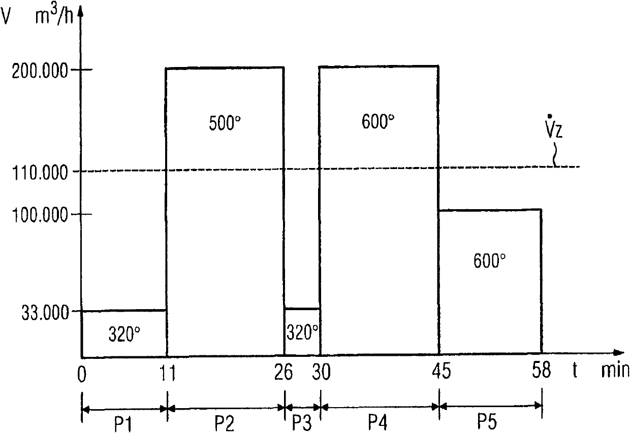
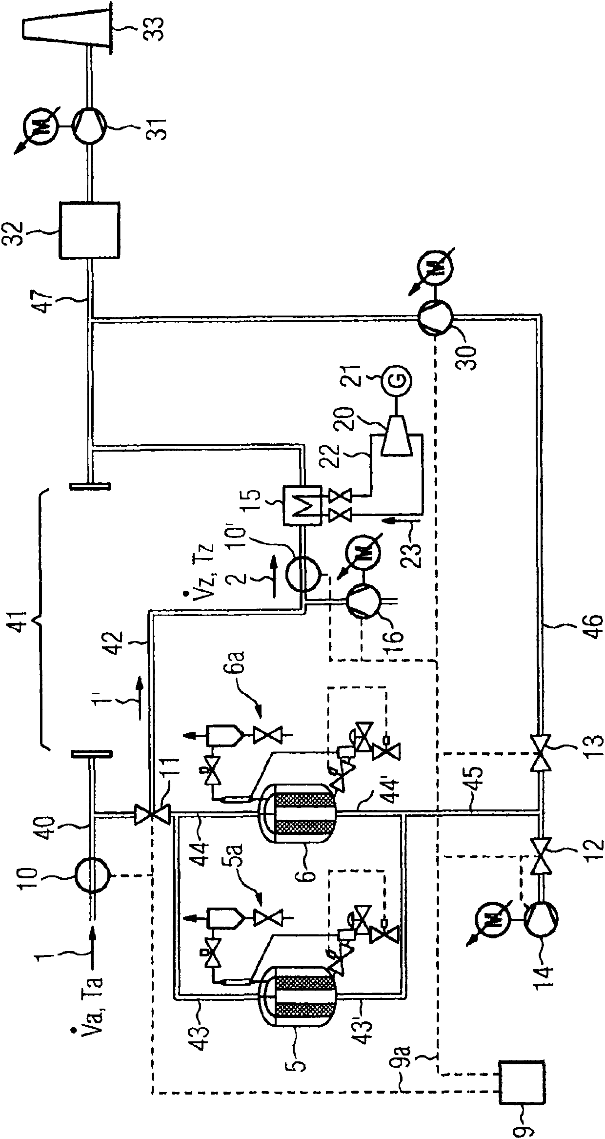
[0025] figure 1 The time curve of the volume flow of the discontinuous exhaust gas flow is shown (see below figure 2 denoted by 1), as it does in the exhaust gas stream produced by the operation of the electric arc furnace in a steel plant. Depending on the operating phase of the furnace, the exhaust gas flow has different volume flows and exhaust gas temperatures in successive operating phases P1 to P5 , but they are constant within an operating phase.

[0026] In the first operating phase P1, liquid steel flows out and fills the first waste basket again. During this phase P1, which lasts 11 minutes, the exhaust stream 1 has 33000m 3 / h volume flow and a temperature Ta of 320°C.

[0027] In the following second operating phase P2, the first melting process takes place, in which due to the volume flow and the jump in temperature Ta make the transition to this second operating phase P2 obvious. In the second operating phase P2, exhaust gas flow 1 has a duration of 15 m...


PUM


Abstract

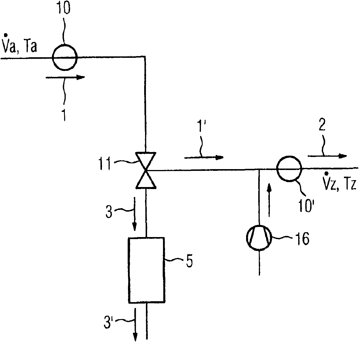
The invention relates to a method and a device for utilizing heat transported by a discontinuous flow of exhaust gases (1), wherein the discontinuous flow of exhaust gases (1) is emitted in phases (P1, P2, P3, P4, P5) with, in each case, constant output values for volume flowing (Va) and temperature (Ta)from an industrial installation, particularly an industrial furnace, wherein the discontinuousflow of exhaust gases (1) is converted into a continuous working flow (2) with adjustable, constant target values for the volume flowing (Vz) and the temperature (Tz). The continuous working flow (2),with the heat contained therein, is used for the conversion of thermal energy into useful energy.

Description

technical field [0001] The invention relates to a method and a device according to claim 1 or claim 10 for utilizing the heat conveyed by a discontinuous exhaust gas flow. Background technique [0002] In industrial furnaces (for example in the steel industry) very high temperatures develop in the exhaust gases during operation, especially in melting processes, for example in electric arc furnaces. Before the exhaust gas is conveyed through the filter into the surrounding environment, the temperature of the exhaust gas is lowered by means of a water cooling circuit in the exhaust pipe or flue or by introducing additional water into the mass flow of the exhaust gas. The cooling of the high temperature of the exhaust gas is necessary for the subsequent exhaust gas cleaning device, because only a certain exhaust gas temperature can achieve an effective cleaning effect. This has the disadvantage that electrical energy must be applied to operate the cooling circuit. [0003] Th...

Claims


Application Information

Patent Timeline
Patent Type & Authority Applications(China)
IPC IPC(8): F27D17/00
CPCF23J15/06F23M99/00F28D2020/006C21C2100/06Y02E20/18F27D17/004F27D17/003Y02E20/363Y02E20/346C21C5/5294F28D20/00F23M20/00Y02E20/30Y02P10/20Y02P10/32
Inventor H·加比J·伦格特T·马特舒拉特
Owner SIEMENS AG
Learn More