Methods for performing model-based lithography guided layout design

A layout and guide map technology, applied in microlithography exposure equipment, original components for photomechanical processing, photomechanical equipment, etc., to achieve the effect of improving process margin, fast cost and improving ability

Active Publication Date: 2010-03-24
ASML NETHERLANDS BV
View PDF7 Cites 17 Cited by
  • Summary
  • Abstract
  • Description
  • Claims
  • Application Information

AI Technical Summary

Problems solved by technology

However, typical chip designs consist of many patterns with complex two-dimensional geometries, and there are no simple rules that can provide a design that avoids wrong placement of the layout (for example due to forbidden spacing) and utilizes space efficiently.

Method used


Image

  • Methods for performing model-based lithography guided layout design
  • Methods for performing model-based lithography guided layout design
  • Methods for performing model-based lithography guided layout design

Examples


Embodiment Construction

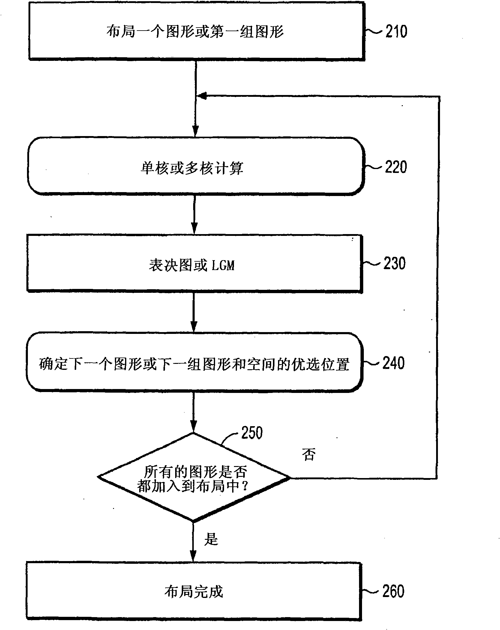
[0044] figure 2 is an exemplary flowchart illustrating an exemplary procedure of the LGL process of the present invention. In a first step of the process (step 210 ), a target design is employed, and one or more features contained in the target design are arranged in a mask pattern according to their corresponding positions in the target pattern. Note that the number of features to be added to the mask pattern from the target pattern in each iteration can be determined, for example, by the operator, or be limited to some fixed number, or can be determined by the process employed and in the target design. Controlling for the number of features considered important in . In other variants, only one feature may be added per iteration.

[0045] At step 220, a simulation of the illumination of the current mask pattern for a given lithographic process (i.e., the process used to illuminate the target pattern) is performed to form an aerial image (or its equivalent) showing the curre...


PUM

PropertyMeasurementUnit
critical dimensionaaaaaaaaaa

Abstract

Methods are disclosed to create efficient model-based Sub-Resolution Assist Features (MB-SRAF). An SRAF guidance map is created, where each design target edge location votes for a given field point onwhether a single-pixel SRAF placed on this field point would improve or degrade the aerial image over the process window. In one embodiment, the SRAF guidance map is used to determine SRAF placementrules and / or to fine-tune already-placed SRAFs. The SRAF guidance map can be used directly to place SRAFs in a mask layout. Mask layout data including SRAFs may be generated, wherein the SRAFs are placed according to the SRAF guidance map. The SRAF guidance map can comprise an image in which each pixel value indicates whether the pixel would contribute positively to edge behavior of features in the mask layout if the pixel is included as part of a sub-resolution assist feature.

Description

[0001] Cross References to Related Applications [0002] This application claims priority to U.S. Patent Application 11 / 757,805, entitled "Method and System for Model-Based Sub-Resolution Assisted Feature Generation," filed June 4, 2007, and also claims Priority to U.S. Provisional Application No. 60 / 935,713 filed on . technical field [0003] The present invention relates to a resolution enhancement technique for lithography, and more particularly, to a system and method for model-based lithography-guided layout. Background technique [0004] For example, lithographic equipment may be used in the manufacture of integrated circuits (ICs). In this case, the mask can contain a circuit pattern corresponding to a single layer of the IC, and this pattern can be imaged onto a substrate (silicon wafer) that has been coated with a layer of radiation-sensitive material (resist) on the target portion (eg, including one or more dies). Typically, a single wafer will contain the entir...

Claims


Application Information

Patent Timeline
Patent Type & Authority Applications(China)
IPC IPC(8): G03F1/14G03F7/20G03F1/00G03F1/36
CPCG03F7/70666G03F7/70441G03F1/36G03F7/70433G03F1/144G03F1/68G03F7/20G06F30/20
Inventor 叶军曹宇冯函英
Owner ASML NETHERLANDS BV
Why Eureka
Try Eureka